8
Safety and Warnings
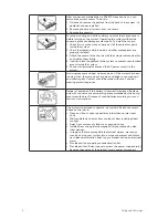
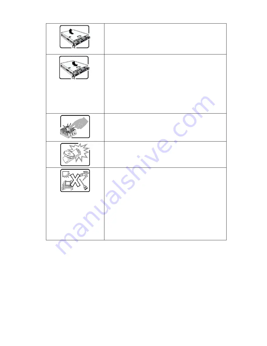
After you have completed the six SAFETY steps above, you can
remove the system covers. To do this:
1.
Unlock and remove the padlock from the back of the system if a
padlock has been installed.
2.
Remove and save all screws from the covers.
3.
Remove the cover(s).
For proper cooling and airflow, always reinstall the chassis covers
before turning on the system. Operating the system without the
covers in place can damage system parts. To install the covers:
1. Check first to make sure you have not left loose tools or parts
inside the system.
2. Check that cables, add-in boards, and other components are
properly installed.
3. Attach the covers to the chassis with the screws removed earlier,
and tighten them firmly.
4. Insert and lock the padlock to the system to prevent unauthorized
access inside the system.
5. Connect all external cables and the AC power cord(s) to the
system.
A microprocessor and heat sink may be hot if the system has been
running. Also, there may be sharp pins and edges on some board
and chassis parts. Contact should be made with care. Consider
wearing protective gloves.
Danger of explosion if the battery is incorrectly replaced. Replace
only with the same or equivalent type recommended by the equip-
ment manufacturer. Dispose of used batteries according to manu-
facturer‘s instructions.
The system is designed to operate in a typical office environment.
Choose a site that is:
• Clean and free of airborne particles (other than normal room
dust).
• Well ventilated and away from sources of heat including direct
sunlight.
• Away from sources of vibration or physical shock.
• Isolated from strong electromagnetic fields produced by elec-
trical devices.
• In regions that are susceptible to electrical storms, we recom-
mend you plug your system into a surge suppressor and discon-
nect telecommunication lines to your modem during an electrical
storm.
• Provided with a properly grounded wall outlet.
• Provided with sufficient space to access the power supplycord(s),
because they serve as the product‘s main power disconnect.
Summary of Contents for SN 40 M1
Page 1: ...User Guide MAXDATA SN 40 M1 Rev 1 1...
Page 2: ...2 Contents...
Page 6: ...6...
Page 32: ...32...
Page 84: ...84...


