


Wartungs- und Reparaturanleitung
BETASTAR
Maintenance and Repair Instructions
1131 / 1211 / 1223
9490.6154 03
11.10.99
Seite/Page:
2.10
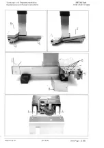
2.10. Austausch von Stößel, Feder und Gummipuffer (nur bei Varianten mit T-Fuß)
Stößel (9) können erst nach Demontage von Nocken (5) und Tritthebelachsen (10) ausgebaut
werden.
Gummipuffer (13) mit Schraubendreher aus Halterung (14) herausheben.
Freigewordene Senkschrauben herausdrehen, mit Stift seitlich am Stößel gegenhalten,
Halterung (14) entfernen.
Stößel (9) und Feder (15) nach oben herausziehen.
Hinweis:
Es empfiehlt sich beim Stößelaustausch den Gummipuffer (13) generell durch einen
neuen zu ersetzen.
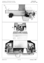
2.11. Austausch der Tritthebelachse zur Querfahrbarkeit (nur bei Varianten mit T-Fuß)
Zylinderschrauben (16) lösen.
Radführung (17) entfernen.
Radhalterung (18) nach unten drücken.
Große und kleine Sicherungsscheibe (19) radial von Tritthebelachse (20) abziehen.
Tritthebelachse (20) nach außen wegziehen (mit Bolzenzieher aus Werkzeugkoffer)
Tritthebel (21), Nocken (22) und Distanzhülsen (23) von Tritthebelachse (20) abziehen
(Paßfedern entfernen)
Tritthebelachse (20) aus T-Fuß herausziehen.
Montage erfolgt in umgekehrter Reihenfolge.
Führung der Radhalterung sowie Nocken einfetten.
2.10 Replacing the tappet, spring and rubber stopper (models with T-shaped base only)
The tappets (9) can be removed only after disassembling the cam (5) and the pedal shafts (10).
Use a screwdriver to pry the rubber stopper (13) out of its seat (14).
Unscrew the countersunk screw thus revealed, support with a pin at the side of the tappet and remove the seat
(14).
Remove the tappet (9) and the spring (15) by pulling upward.
Note:
It is generally advisable to replace the rubber stopper (13) any time the tappet is replaced.
2.11 Replacing the shaft at the pedal controlling transverse movement (models with T-shaped base only)
Unscrew the machine screws (16).
Remove the castor guide (17).
Press the castor holder (18) downwards.
Remove the large and small retaining rings (19) to the side, off the pedal shaft (20).
Pull the pedal shaft (20) outward (using the pin extractor from the tool kit).
Remove the pedal (21), the cam (22) and the spacer bushing (23) from the pedal shaft (20) (remove the keys to do
so).
Pull the pedal shaft (20) out of the T-shaped base.
Reassemble in reverse order.
Grease the castor holder and the cam.
Summary of Contents for Betastar 1131
Page 1: ......
Page 6: ......
Page 8: ......
Page 10: ......
Page 12: ......
Page 14: ......
Page 16: ......
Page 18: ......
Page 20: ......
Page 22: ......
Page 24: ......
Page 26: ......
Page 28: ......
Page 30: ......
Page 32: ......
Page 34: ......
Page 36: ......
Page 38: ......
Page 40: ......
Page 42: ......
Page 44: ......
Page 46: ......
Page 48: ......
Page 50: ......
Page 52: ......
Page 54: ......
Page 56: ......
Page 58: ......
Page 60: ......
Page 62: ......
Page 64: ......
Page 66: ......
Page 68: ......
Page 70: ......
Page 72: ......
Page 74: ......
Page 76: ......
Page 78: ......
Page 80: ......
Page 82: ......
Page 84: ......
Page 86: ......
Page 88: ......
Page 90: ......
Page 92: ......
Page 96: ......
Page 111: ......
Page 112: ......
Page 113: ......
Page 114: ......
Page 115: ......
Page 116: ......
Page 117: ......
Page 118: ......
Page 119: ......
Page 120: ......
Page 121: ......
Page 122: ......
Page 123: ......
Page 126: ......
Page 127: ......
Page 128: ......
Page 129: ......
Page 130: ......
Page 131: ......
Page 132: ......
Page 133: ......
Page 134: ......
Page 135: ......
Page 136: ......
Page 137: ......
Page 138: ......
Page 139: ......
Page 140: ......
Page 141: ......
Page 142: ......
Page 143: ......
Page 144: ......
Page 145: ......
Page 146: ......
Page 147: ......
Page 148: ......
Page 149: ......
Page 150: ......
Page 151: ......
Page 152: ......
Page 153: ......
Page 154: ......
Page 155: ......
Page 156: ......
Page 157: ......
Page 158: ......
Page 159: ......
Page 160: ......
Page 161: ......
Page 162: ......
Page 163: ......
Page 164: ......
Page 168: ...Prüfanleitung Fehlersuche Hydraulische OP Tische 9491 0354DE 02 10 06 2000 Seite Page 1 01 ...
Page 174: ...Prüfanleitung Fehlersuche Hydraulische OP Tische 9491 0354DE 02 10 06 2000 Seite Page 2 05 ...
Page 178: ...Prüfanleitung Fehlersuche Hydraulische OP Tische 9491 0354DE 02 10 06 2000 Seite Page 3 01 ...
Page 180: ...Prüfanleitung Fehlersuche Hydraulische OP Tische 9491 0354DE 02 10 06 2000 Seite Page 3 03 ...
Page 182: ...Prüfanleitung Fehlersuche Hydraulische OP Tische 9491 0354DE 02 10 06 2000 Seite Page 3 05 ...
Page 184: ...Prüfanleitung Fehlersuche Hydraulische OP Tische 9491 0354DE 02 10 06 2000 Seite Page 3 07 ...
Page 186: ...Prüfanleitung Fehlersuche Hydraulische OP Tische 9491 0354DE 02 10 06 2000 Seite Page 4 01 ...
Page 188: ...Prüfanleitung Fehlersuche Hydraulische OP Tische 9491 0354DE 02 10 06 2000 Seite Page 4 03 ...
Page 190: ...Prüfanleitung Fehlersuche Hydraulische OP Tische 9491 0354DE 02 10 06 2000 Seite Page 4 05 ...
Page 225: ......
Page 226: ......
Page 227: ......
Page 228: ......
Page 229: ......
Page 230: ......
Page 231: ......
Page 232: ......