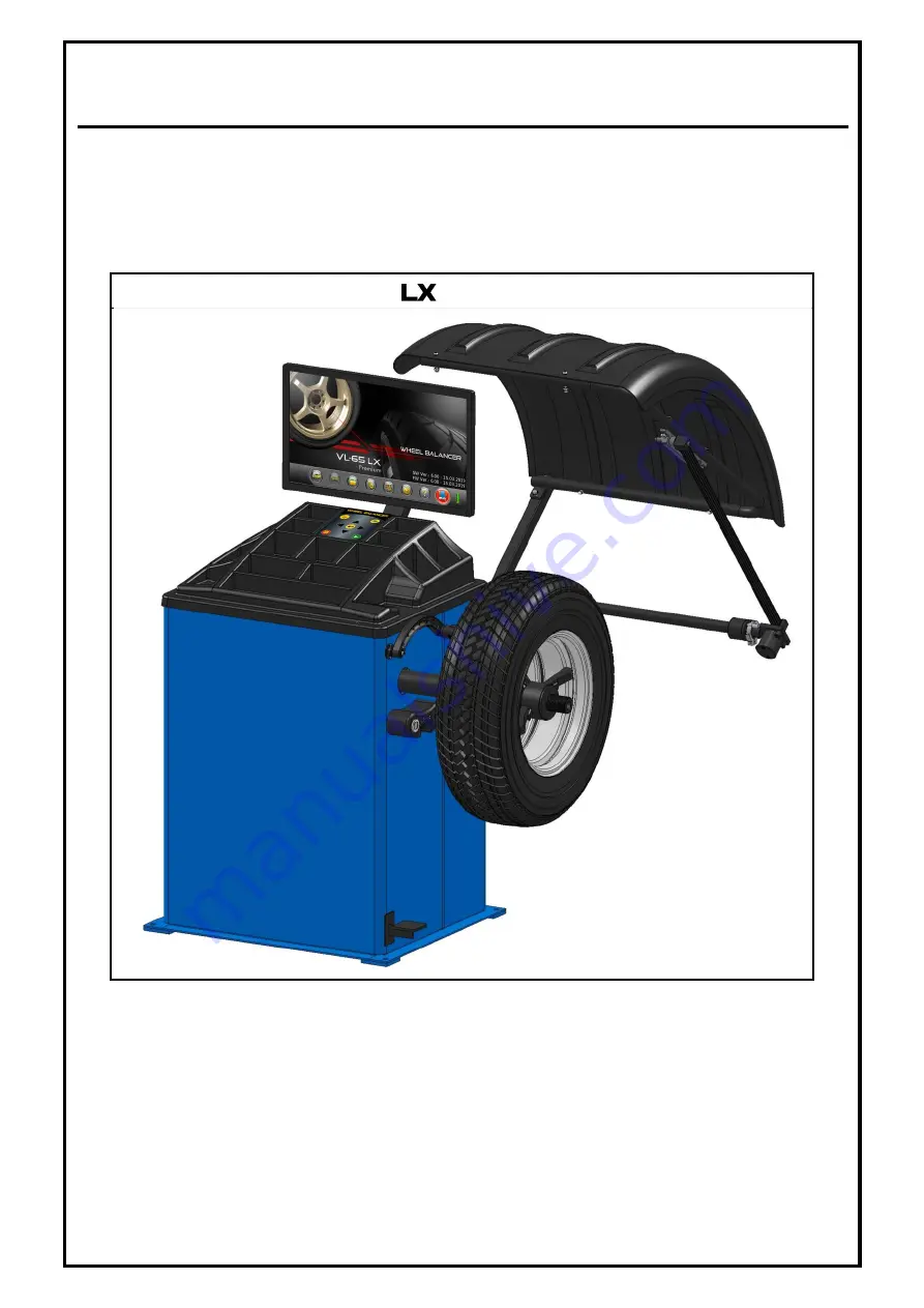
VIDEOGRAPHIC WHEEL BALANCER
WB-VL-65 DSP
Premium
/
OPERATING MANUAL
(Ver.1.6)
Page 1: ...VIDEOGRAPHIC WHEEL BALANCER WB VL 65 DSP Premium Premium OPERATING MANUAL Ver 1 6...
Page 2: ...balancer leaving our Factory is in the best operating condition This OPERATING MANUAL has been prepared to help you in getting the best performance out of the equipment Still if you have any doubt ple...
Page 3: ...3 DISPLAY UNIT 15 6 4 CONTROL PANEL 15 6 5 WHEEL GUARD 15 6 6 STANDARD ACCESSORIES 16 6 7 OPTIONAL ACCESSORIES 17 7 OPERATION 18 7 1 DEFECTS MALFUNCTIONS 18 7 2 PREPARATION OF WHEEL FOR BALANCING 18 7...
Page 4: ...lar the equipment must be installed and operated in protected environments where there is no risk of dripping or direct sunlight 5 Ensure that any equipment which produces Ultra Violet rays is not ava...
Page 5: ...ate accessories for mounting various types of wheels 2 2 SAFETY INSTRUCTIONS FOR COMMISSIONING 1 Only authorized service personnel are allowed to install and commission the Wheel balancer 2 DO NOT HOL...
Page 6: ...o not lift the Wheel guard until the wheel rotation is completely stopped 11 Never overload the Balancer 12 Do not keep heavy objects over the system except limited quantity of Wheel balancing weights...
Page 7: ...eel from hitting the Distance measuring rod while running ie if the Distance measuring rod is not in home position the wheel run will not be carried out and an Error code Distance rod is not in Home p...
Page 8: ...ectrical safety Part No B2945 B2946 Safety instruction for operation II Part No H3635 Indicator for direction of rotation of wheel Part No H3636 Mechanical brake attention Part No H3632 Foundation War...
Page 9: ...balancing sequence 16 Compact simplified Membrane keypad 17 Safety Warning messages 18 On screen help notes messages 19 Fully automatic start measurement and braking 20 Static Single plane Dynamic Tw...
Page 10: ...z 0 35HP 1 60 50Hz 2 Motor speed 230V 50 60Hz operation 110V 60 50Hz operation 960rpm 1200rpm 3 Power supply 230V 50 60Hz operation 110V 60 50Hz operation 230VAC 10 1 50 60Hz N PE 110VAC 10 1 60 50Hz...
Page 11: ...ly to the equipment must be connected through a CE certified MCB with ratings as given below For 230V 50 60Hz operation Two pole Type C 6A MCB For 110V 60 50Hz operation Two pole Type C 10A MCB Proper...
Page 12: ...ackage contents Qty 1 Main cabinet corrugated box 1 Main cabinet assembly 1 No 2 Monitor 1 No 3 Monitor column 1 No 4 Wheel guard with pipe DMR 1 No 5 Width caliper 1 No 6 Width measuring rod 1 No 7 A...
Page 13: ...M16 Spring washer Flat type between the Cabinet and Floor 5 Fix the Cabinet with foundation bolts using Nut Washer that comes along with Anchor bolt 6 Check of any tilt Use required quantities thickne...
Page 14: ...5 Bring the Width assembly cable through the bracket and connect Male end of Wire from Width measuring rod to female end provided below the Bracket at the rear side of cabinet 6 Fix the Safety cover w...
Page 15: ...be carried out Balancing is the process of finding out the Mass which causes unbalance and the location phase of the mass and adding equal weight in the directly opposite location 180 away Fig 7 5 2 S...
Page 16: ...rent based on the configuration of Alloy rim refer Chapter 7 4 1 The Diameter Width of the Rim and the Rim distance are the inputs to the equipment for calculating the unbalance When the distance from...
Page 17: ...d Control panel Mains power cable is situated at the rear side of Cabinet ON OFF switch is provided at side of cabinet Control fuses are incorporated to protect electronic assemblies against short cir...
Page 18: ...ns To select the SETTINGS button in WELCOME screen To proceed with next step screen in balancing operations To clear error messages Pressing the key twice within a second will start balancing operatio...
Page 19: ...Medium taper Min 52 5 Max 70mm Code P9363 Wheel seating dual cone Medium taper Min 66 Max 83 5mm Code P9364 Wheel seating dual cone Medium taper Min 80 Max 97 5mm Code P9365 Wheel seating dual cone M...
Page 20: ...e 157mm Code A2826 Wheel seating cone with spacer Tata 407 For Wheel bore 162mm Code A2827 Wheel seating cone Taper 2 23 Code P9226 Wheel seating cone Taper 2 58 Code P9227 Wheel seating cone Taper 2...
Page 21: ...after clearing the indicated error 7 1 DEFECTS MALFUNCTIONS In case of defects or malfunctions such as abnormal noise improper display Keypad not responding etc turn OFF the mains and contact qualifie...
Page 22: ...th bigger dia end butting against the MCD Slide the Wheel seating cone on to the MCD shaft with its larger diameter butting against the MCD face as shown in Fig 13 Lift the wheel on to the shaft and c...
Page 23: ...im Lift the wheel on to the shaft and slide it to butt against the Spacer Position the cone onto the centre hole diameter of the rim and insert it to the shaft along with the wheel Insert the QCLN wit...
Page 24: ...eels with 5 mounting holes Fig 16 Measure the pitch distance of the mounting hole in the wheel using PCD measuring tool provided and tighten the measuring tool in the same position without disturbing...
Page 25: ...3 Alloy wheels Balancing weights is applied on the Inner plane only Split weight functions cannot be done in Static balancing mode Switch ON the equipment and wait for a minute approx Program will loa...
Page 26: ...ed If the Job count reaches maximum count of 99999 a message will be prompted the system will reset the count to 00001 automatically 7 4 1 RIM PARAMETERS While setting Rim parameters using Navigation...
Page 27: ...th then the Rim type ALU4 ALU 5 Steel will be detected automatically depending on location of measurement Automatic Rim type detection is applicable only in Dynamic mode The Distance Dia measuring rod...
Page 28: ...ollowed by an Audio indication Rim selection The selected Rim type will be displayed in the Status bar of RIM PARAMETERS screen Wheel Rim types Steel rims Clip on weights for both Inner and Outer plan...
Page 29: ...f the Laser line If Weight Calibration data is not available Redo weight calibration or Restore Factory calibration message is displayed press key to clear message Calibration to be done before procee...
Page 30: ...tion only The Torch can be switched On Off as desired by using button In Laser mode unbalance position will be indicated for Inner Inner most position Repeat the above steps for Outer plane also Spin...
Page 31: ...s key Following screen will be displayed Fig 26 No of spokes that can be accommodated is min of 3 spokes max of 12 spokes Select the appropriate Nos of Spokes with respect to the number of spokes avai...
Page 32: ...the wheel as explained in Chapter 7 4 2 or press key to exit from Split weights program to go to WHEEL RUN screen 7 5 2 OPTIMIZATION FUNCTION Optimization is normally done to reduce the Static unbala...
Page 33: ...ompleted close the Wheel guard or press key twice Optimization completed message will be displayed the system will go to POSITION TRACKING screen and run the wheel automatically To exit from Optimizat...
Page 34: ...or Disabling Buzzer indication throughout balancing program Settings Enabling or Disabling Auto run function in Wheel balancing operation Enabling or Disabling Automatic Distance measurement Enabling...
Page 35: ...nsure the foundation is proper 2 Ensure the Cabinet is free from shake 3 Check the Belt tension and RPM The RPM should be 175 20 5 Pre calibration Applicable for Factory Authorized Engineer Following...
Page 36: ...im dia 16 Unbalance should be 50gm min For Single point use a fairly balanced wheel with Rim dia 12 24 Unbalance should be 30gm min Use keys to move to next parameters Two point calibration Low Point...
Page 37: ...nd ensure wheel mounted is with minimum unbalance To know the millivolts of Raw calibration after completing Tyre zero press key to go to RAW CALIBRATION run the wheel to view millivolts of SA SB disp...
Page 38: ...ration if Calibration weight signal is too high Press Key to proceed or any other key to exit error message appears check whether the correct calibration weight is added on the appropriate plane or we...
Page 39: ...played voltage is not within specification loosen the lever fixing Allen screw and Grub screw to move the DMR slightly and then rotate the Lever fixing rod till required voltage is set Touch the Beari...
Page 40: ...ie Stopper Position and ensure the displayed Width voltage Outer Dia voltage is 1 00V 0 1V 2 50V 0 1V respectively If the displayed Outer dia voltage is not within specification move the Width assembl...
Page 41: ...Touch the Width rod at the top edge of MCD and hold it for few seconds till Audio indication and then move the Width rod to Home position The system will go to WIDTH CALIBRATION screen Select WHEEL C...
Page 42: ...in RIM PARAMETERS screen are as per the Wheel Width specifications within tolerance limit of 0 3 9 4 WHEEL TRACKING TEST This feature should be used only by authorised Service personnel Hence User sh...
Page 43: ...module 9 14 RESTORE FACTORY CALIBRATION This feature should be used only by authorised Service personnel Hence User should not enter into this module 9 15 WEIGHT CUTOFF This feature should be used on...
Page 44: ...nting and removing which may affect the accuracy of the equipment Apply a thin layer of machine oil on the MCD flange and shaft for rust prevention Wipe off the excessive oil and keep them clean DO NO...
Page 45: ...nnection 5 Spark in the Mains cord socket Loose connection in the AC supply socket Connect the power mains with proper plug socket combination 6 Wheel is not balanced and repeatedly asking weights Imp...
Page 46: ...pecified range Use fairly balanced wheel and do the calibration 14 Width rod is not in Home position The Width rod may not be at home position Ensure that the Width rod is in home position Check for t...
Page 47: ......
Page 48: ...acturer All information illustrations and specifications contained in this Manual are based on the latest information available at the time of publication Manufacturer reserves the right to make chang...