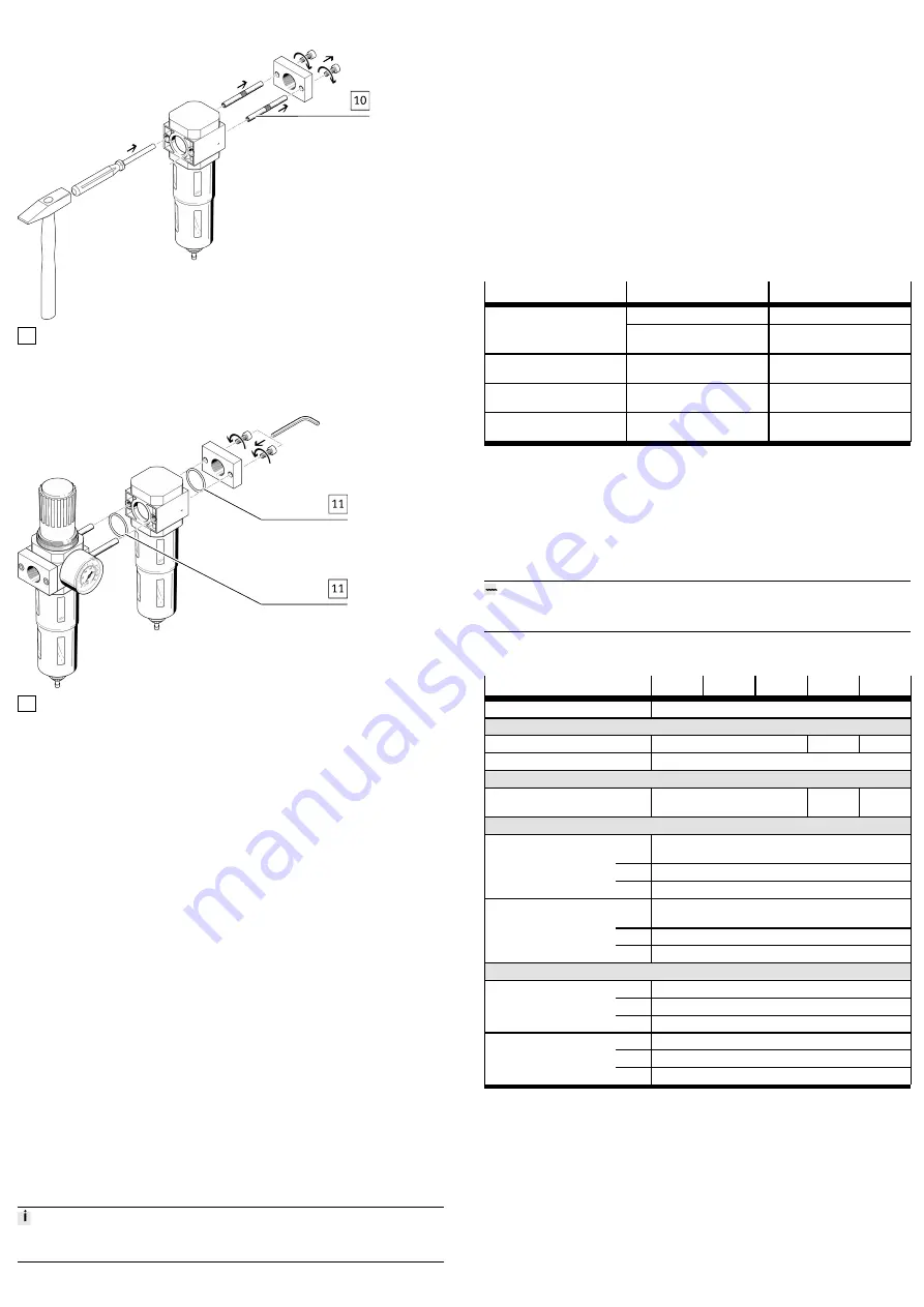
2. Screw in threaded bolt FRB-D
. Tightening torque: 2.5 – 0.5 Nm
10 Spacer bolts
Fig. 4 LR(S)
3. Remove the sub-base on the respective add-on product. Drive out the corres-
ponding spacer bolts
. Driving action in flow direction.
11 Seal
Fig. 5 LFR(S)/LR(S)
4. Mount the add-on product with the sub-base. There must be one seal
each
between the add-on products and the sub-base.
7
Pneumatic Installation
1. Fittings, seals, suitable hoses: accessories
è
2. Screw fittings into the pneumatic ports.
3. Push suitable hoses into the fitting up to the stop.
–
Position hoses axial to the pneumatic ports.
–
Do not exceed the minimum bending radius for the hoses.
8
Setting the Outlet Pressure
(pull).
2. Turn the rotary knob completely in the – direction.
3. Exhaust system slowly: turn the rotary knob in the + direction until the
desired pressure is reached.
Maintain permissible pressure regulation range
è
The input pressure p1 should always be at least 1 bar higher than the set out-
let pressure p2.
4. Lock the rotary knob
9
Maintenance
9.1
Draining the Condensate
Manually Draining the Condensate
If the condensate reaches a level approx. 10 mm below the filter element:
1. Turn drain screw
anticlockwise as seen from below.
Ä
The condensate flows out.
2. Turn drain screw clockwise as seen from below.
Automatic Draining of the Condensate LFR(S)/LF...-...-A
The filter drains automatically.
9.2
Changing the Filter
Replace the filter cartridge if the flow rate is reduced even though the pressure
setting is unchanged.
1. Exhaust compressed air from the product.
3. Disassemble the old filter cartridge:
–
LFR(S)/LF: unscrew the filter plate and remove the filter cartridge.
–
LFM.../LFX: unscrew the filter cartridge.
4. Install new filter cartridge:
–
LFR(S)/LF: place filter cartridge on the filter plate. Screw filter plate in
until it stops.
–
LFM.../LFX: hold filter cartridge at the bottom. Screw filter cartridge in
until it stops.
5. Screw in filter bowl. Tightening torque: MINI: 2 Nm, MIDI/MAXI: 2.5 Nm.
9.3
Cleaning
•
Clean the outside of the product as required with a soft cloth.
Permissible cleaning agents:
–
Soap suds (max. +60 °C)
–
Petroleum ether (free of aromatic compounds)
10
Fault Clearance
Error description
Cause
Remedy
Constriction in the supply line
Check supply line
Low flow rate (operating pres-
sure breaks down with air con-
sumption)
Filter cartridge is dirty
Replace filter cartridge
è
Pressure increases above the
set working pressure
Valve disc defective at sealing
seat
Replace product
Audible, continuous blowing
noise at rotary knob
Valve seat damaged
Replace product
Blowing noise can be heard at
the drain screw.
Drain screw leaking
Replace product or filter bowl
Tab. 2 Fault Clearance
11
Disassembly
1. Exhaust the complete system and product.
2. Release interlock at the fittings by pressing it and pull out hose assembly.
3. Release fittings at the connecting flanges and unscrew.
12
Disposal
ENVIRONMENT!
Send the packaging and product for environmentally sound recycling in accord-
ance with the current regulations
è
13
Technical Data
Product
LFR(S)
LR(S)
LF
LFM
LFX
Mounting position
[°]
Ve/–5
Temperature ranges
Temperature of medium
[°C]
–10 … +60
1.5 … 60
5 … 30
Ambient temperature
[°C]
–10 … +60
Operating medium
Compressed air to ISO
8573-1:2010
[-:9:-]
[6:8:4]
[1:4:2]
Input pressure
Without fully automatic con-
densate drain
[MPa]
£
1.6
[bar]
£
16
[psi]
£
232
With fully automatic con-
densate drain
[MPa]
0.2 … 1.2
[bar]
2 … 12
[psi]
29 … 174
Pressure regulation range
For LFR(S)/LR(S)-...-D-7
[MPa]
0.05 … 0.7
[bar]
0.5 … 7
[psi]
7 … 101
For LFR(S)/LR(S)-...-D
[MPa]
0.05 … 1.2
[bar]
0.5 … 12
[psi]
7 … 174
Tab. 3 Technical Data
Summary of Contents for MPJ Series
Page 6: ...6 BA550001 en Blank page...
Page 13: ...BA550001 en 13 6 Technical data 6 1 Relevant pit dimensions...
Page 29: ...BA550001 en 29 10 mm...
Page 35: ...BA550001 en 35...
Page 39: ...BA550001 en 39 I F H G J A E C D K B...
Page 114: ...20 PL670000_002 de...


