background image

®

For additional information, see the complete installation and operation guide at 

www.lutron.com/qs

GRAFIK Eye

®

 QS Control Unit Quick Installation and Operation Guide   19
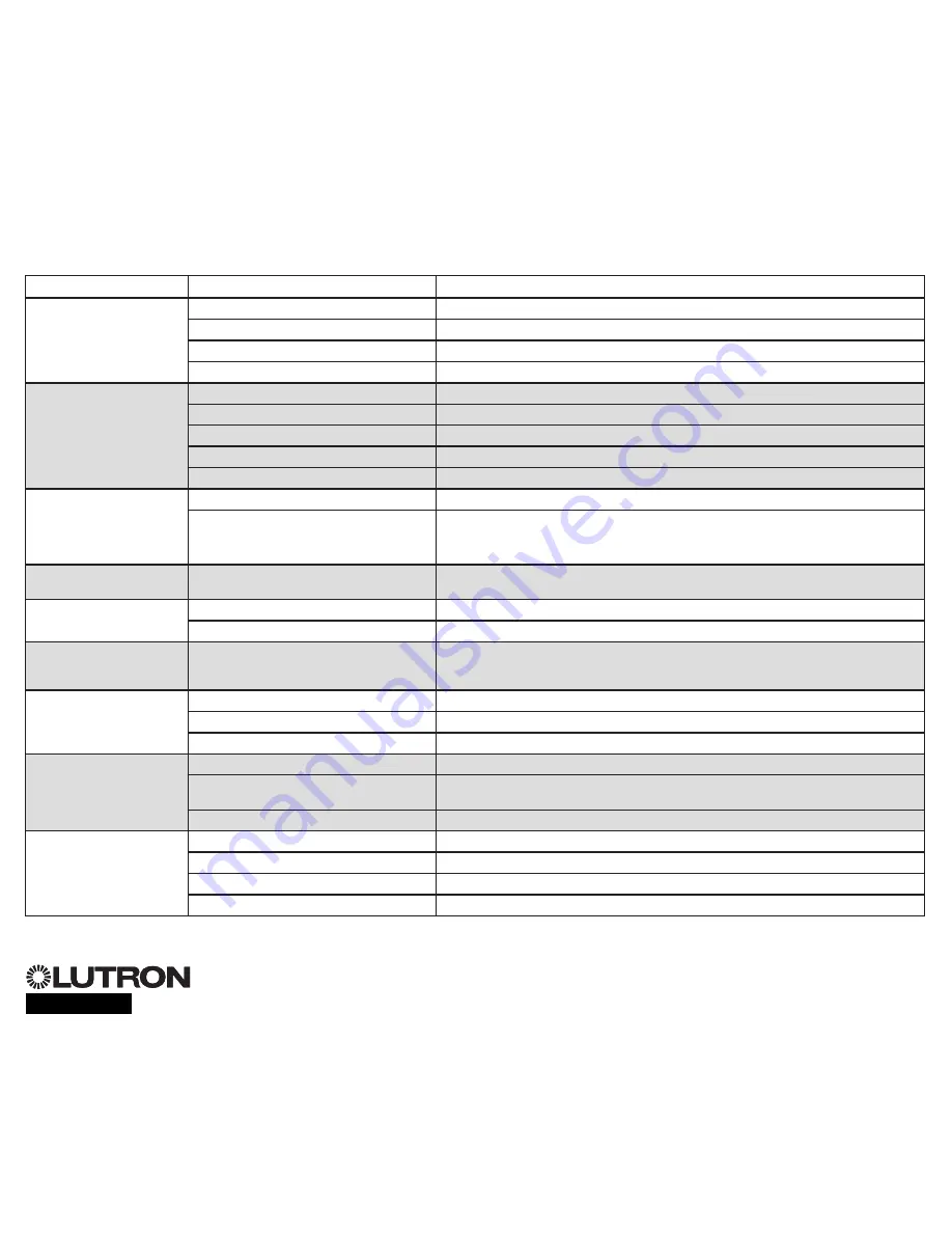
Troubleshooting

Symptom

Possible Causes

Solution

Unit does not power up
Unit does not control loads
Circuit breaker is tripping

Circuit Breaker is off

Switch circuit breaker on

Miswire

Verify wiring to unit and loads

System short circuited

Find and correct shorts

System overload

Verify zone/unit loading is within ratings (see Zone Setup section)

Zone control does not work
Zone control yields incorrect 

results

Miswire

Make sure loads are connected to the right zones

Loose or disconnected wire

Connect zone wires to loads

Burned out lamps

Replace bad lamps

Incorrect load type selected

Assign the zone to the appropriate load type (see Zone Setup section)

Dimming limits set incorrectly

Adjust High End/Low End values  (see Zone Setup section)

One or more zones are 

always “full on” and zone 

intensity is not adjustable

Zone control affects more 

than one zone

Miswire

Make sure loads are connected to the right zones

Shorted line output

Check wiring; if wiring is correct, call Lutron Technical Support

Faceplate is warm

Normal operation

Solid-state controls dissipate about 2% of the connected load as heat.  No action is required

Unit does not allow scene 

change or zone adjustments

Unit is in wrong save mode

Change to correct save mode

QS device in system has locked the unit

Check programming and state of QS devices

Cannot program fade time 

from “Scene Off”

Fade time from “Scene Off” is not 

programmable; can only program fade time to 

“Scene Off”

Fade time from “Scene Off” is always 3 seconds

Integral (direct-wired) contact 

closure input does not work

Miswire

Check wiring on contact closure input

Input CCI signal is not received

Verify the input device is operating properly

Unit is in wrong CCI mode and/or type

Change to correct CCI mode and/or type for your application

QS devices on link are not 

working

Miswire or loose connection on QS link

Verify QS link wiring to all devices

QS device is not associated

Place the QS device into programming mode, and hold the “Scene 1” button on the  

GRAFIK Eye

®

 QS control unit to associate the two devices

QS device programming is incorrect

Verify the functionality and programming on the QS devices

Timeclock events do not 

occur
Sunrise or sunset events do 

not occur at the correct time

Timeclock is disabled

Enable the timeclock

Time/date is not set correctly

Set the time/date

Location is not set correctly

Set the latitude and longitude of the unit’s location

Holiday schedule is in effect

Normal schedule will resume when the holiday ends

Summary of Contents for QSGR-3PCE

Page 1: ...Navigating Menus in Programming Mode 10 Wireless Mode 11 Zone Setup Assigning Load Types 12 Assigning Non Dim Load Type 12 Setting Load Types 13 Scene Setup Setting Zone Levels Fade Rates and Window...

Page 2: ...evels Timeclock button Displays current timeclock info OK button Used for programming Infrared receiver For handheld remote use Master buttons Temporarily raise and lower lighting levels on unit USB t...

Page 3: ...GRAFIK Eye QS Control Unit Overview of Line Voltage Mains Wiring 1 2 3 4 1 2 A B C 1 2 3 4 5 6 L N 4 0 mm2 each terminal 230 V Distribution Panel Line Voltage Mains Cables and Load Wiring 1 2 3 4 5 6...

Page 4: ...F at the circuit breaker or fuse box Connect a standard light switch between the live lead and load wire to test the circuit Turn power ON and check for short or open circuits If load does not operate...

Page 5: ...ntrol unit to properly recognize them Notice Risk of damage to unit GRAFIK Eye QS control units must be in stalled by a qual i fied electrician in accordance with all applica ble reg u la tions and bu...

Page 6: ...rminals 3 and 4 Twisted shielded pair 0 5 mm2 each terminal 24 V 100 mA Common and power terminals 1 and 2 Two 1 0 mm2 each terminal for link 153 m Two 4 0 mm2 each terminal for link 153 610 m Do not...

Page 7: ...mart power panel LUTRON LUTRON LUTRON LUTRON LUTRON LUTRON T Tap Wiring Example GRAFIK Eye QS control unit Sivoia QS window treatment seeTouch QS wallstation LUTRON LUTRON LUTRON LUTRON LUTRON LUTRON...

Page 8: ...3 and 4 NOT terminal 2 shown by the letter B on the diagram Wiring can be T tapped or daisy chained For additional information see the complete installation and operation guide at www lutron com qs G...

Page 9: ...tton The LED will light Press the zone raise and lower buttons Make sure the control unit is dimming all connected loads 3 Apply the protective overlay to the control unit Note When tightening mountin...

Page 10: ...will either take you to the next menu or accept a setting you have selected When the screen displays a Yes No question the OK button is Yes Timeclock Button The Timeclock button functions as a back bu...

Page 11: ...FIK Eye QS Wireless control unit will respond to any programming commands from nearby Lutron QS wireless and compatible products Ignore Programming default The GRAFIK Eye QS Wireless control unit will...

Page 12: ...t zone Zone Setup Non Dim Load Type Load Type Set zones Saved Load Type Assigning Non Dim Load Type Zones assigned to non dim loads have three available configurations LOFO Last On First Off FOFO Firs...

Page 13: ...ust be used with the control unit Zone ratings Not all zones must be connected however connected zones must have a minimum load of 40 W Maximum loads 10 A per unit 500 W per zone Maximum total lightin...

Page 14: ...lay and the three middle LEDs for the zone will be lit to indicate this zone is unaffected by the scene the zone will not change when this scene is initiated When all zones are at the desired level pr...

Page 15: ...of box functionality Doing so will remove its programming from the GRAFIK Eye QS control unit 7 Repeat the above steps for all desired sensors 8 Exit programming mode Associating wireless occupancy s...

Page 16: ...ress OK Once a sensor has been assigned it will appear with an asterisk in the sensor list Repeat for additional sensors Note If wireless sensors are not found verify that they are associated correctl...

Page 17: ...utomatically turn off the lights after a set time delay Disable this feature by setting the time delay to 0 disabled Range Disabled or 1 30 minutes default Disabled Zone Fade When in Zone Mode lights...

Page 18: ...t level and then press the zone raise and lower buttons simultaneously for 1 second until the zone LEDs flash at the programmed preset level Repeat for all zones you wish to control with the Pico wire...

Page 19: ...issipate about 2 of the connected load as heat No action is required Unit does not allow scene change or zone adjustments Unit is in wrong save mode Change to correct save mode QS device in system has...

Page 20: ...TTEN CONSENT ARISING OUT OF OR IN ANY WAY RELATED TO THE INSTALLATION DEINSTALLATION USE OF OR INABILITY TO USE THE UNIT OR OTHERWISE UNDER OR IN CONNECTION WITH ANY PROVISION OF THIS WARRANTY OR ANY...

Reviews: