


®
For additional information, see the complete installation and operation guide at
www.lutron.com/qs
GRAFIK Eye
®
QS Control Unit Quick Installation and Operation Guide 12
Assigning Load Types
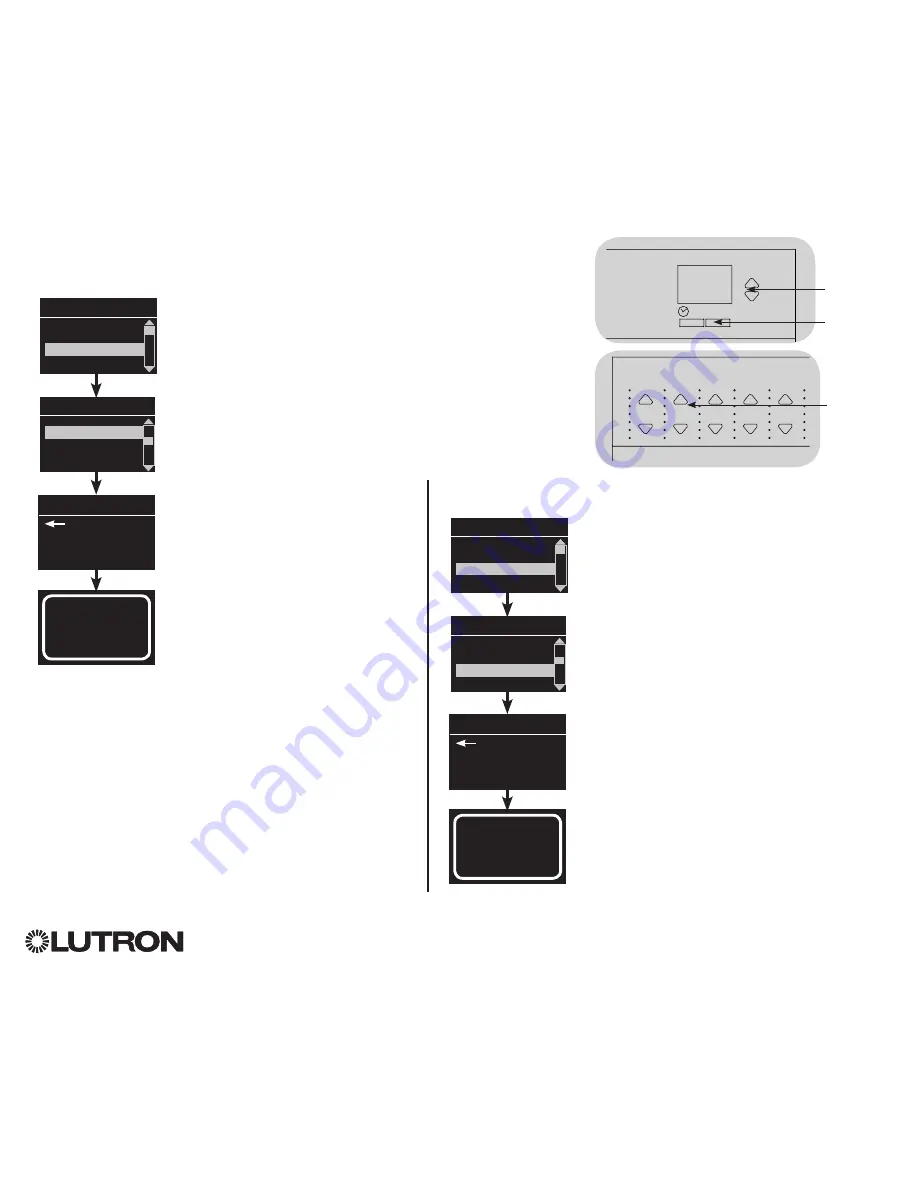
1. Enter programming mode.
2. Use the Master buttons to highlight
“Zone setup” and press the
OK button to accept.
3. Use the Master buttons to highlight
“Load type”. Press the OK button to
accept. See “Setting Load Types”
table on the next page.
4. Use the zone raise/lower buttons to
choose the load type for that zone.
See the list on the next page for
supported load types. Press the OK
button to accept.
5. The info screen will confirm that
your load type has been saved.
6. Exit programming mode.
Zone Setup
OK
1
2
3
4
5
6
Master
buttons
OK button
Main menu
CCI Setup
Zone setup
OK
1
2
3
4
5
6
Use the
zone
raise/lower
buttons to
choose the
load type for
that zone.
Zone Setup
Non-Dim Load Type
Load Type
Set zones
Saved
Load Type
Assigning Non-Dim Load Type
Zones assigned to non-dim loads have three available configurations:
•
LOFO: Last On, First Off
•
FOFO: First On, First Off
•
FOLO: First On, Last Off
Scenes made up of both dim and non-dim
load types will toggle the non-dim loads
before the dim loads in a “First” on/off
configuration, and after the dim loads in a
“Last” on/off configuration.
1. Enter programming mode.
2. Use the Master buttons to highlight “Zone
setup” and press the OK button to accept.
3. Use the Master buttons to highlight “Non-Dim
Load type”. Press the OK button to accept.
See “Setting Load Types” table on the next
page.
4. Use the zone raise/lower buttons to choose
the non-dim load type for that zone. (Zones
not programmed as non-dim will be displayed
as Unaffected.) Press the OK button to
accept.
5. The info screen will confirm that your load
type has been saved.
6. Exit programming mode.
Main menu
CCI Setup
Zone setup
Zone Setup
Load Type
Load Type
Set zones
Saved
Non-Dim Load Type


