background image

®

For additional information, see the complete installation and operation guide at 

www.lutron.com/qs

GRAFIK Eye

®

 QS Control Unit Quick Installation and Operation Guide   15

Associating wireless occupancy sensors and GRAFIK Eye

®

 QS Wireless control units 

(for wireless enabled units only):

1.  Make sure the wireless mode of the GRAFIK Eye

®

 QS control 

unit is “Enabled”.

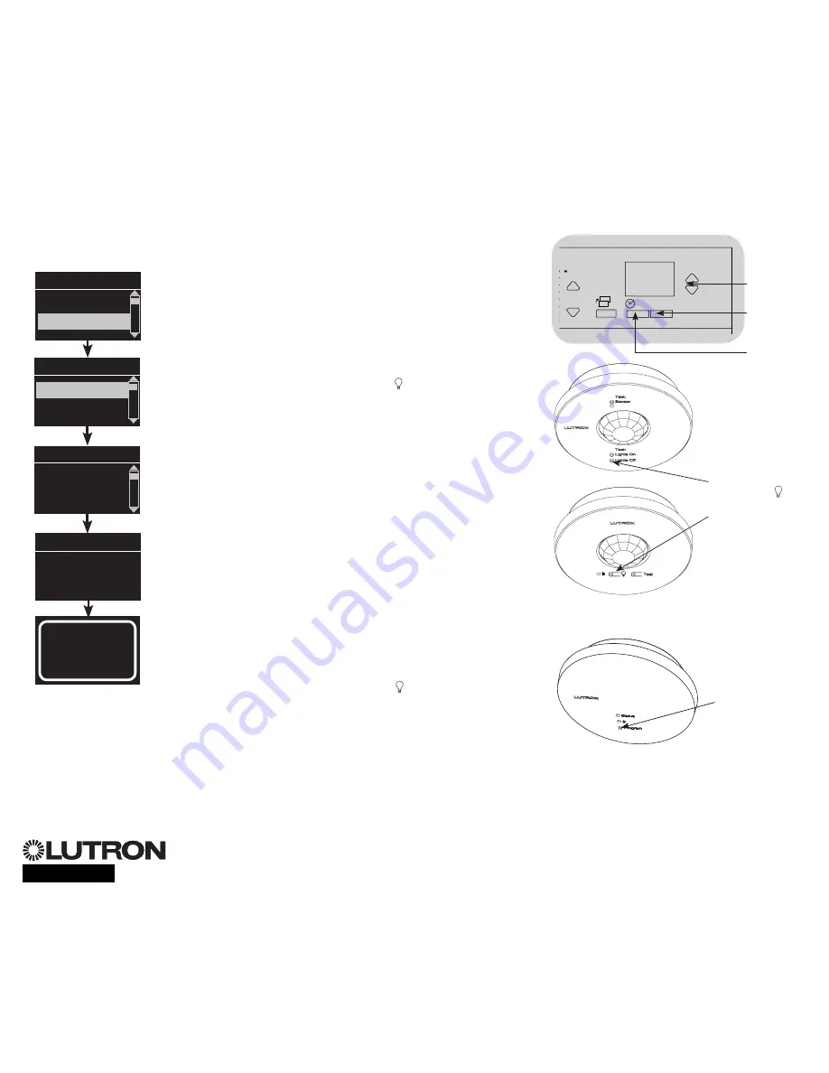
2.  Enter programming mode.
3.  Use the Master buttons to highlight “Sensor setup” and press 

the OK button to accept. 

4.  Use the Master buttons to highlight “Add wireless sensors” and 

press the OK button to accept. 

5.  Press and hold the “Lights Off” button (  on some sensors) on 

the occupancy sensor for 6 seconds. The lens will start flashing 

and the info screen on the GRAFIK Eye

®

 QS Wireless control unit 

will display the sensor’s serial number.

6.  Press the OK button on the 

GRAFIK Eye

®

 QS control unit. A 

screen will confirm that the sensor has been assigned.  

(To disassociate a wireless occupancy sensor from the GRAFIK 

Eye

®

 QS control unit, Refer to the Radio Powr Savr

TM

 occupancy 

sensor install guide to return the sensor to its “out-of-box” 

functionality. Doing so will remove its programming from the 

GRAFIK Eye

®

 QS control unit.)

7. Repeat the above steps for all desired sensors.
8. Exit programming mode.

Associating wireless occupancy sensors through  

QS Sensor Modules (QSM):

1.  Press and hold the Program button on the QSM for 3 seconds 

to enter programming mode. There will be 1 audible beep 

and the Status LED will begin flashing. The info screen on the 

GRAFIK Eye

®

 QS control unit will display that the QSM is in 

programming mode.

2.  Press and hold the “Lights Off” button (  on some sensors) on 

the occupancy sensor for 6 seconds. There will be 3 audible 

beeps from the QSM to verify association.

3.  Press and hold the Program button on the QSM for 3 seconds 

to exit programming mode.

Note:

  The wireless signal has a range of 9 m through standard 

construction or 18 m line of sight.

Occupancy Sensor Setup

OK

1

2

3

4

5

6

9

10

11

12

13

14

7

8

15

16

9-16

1-8

Master 

buttons

OK  

button

Timeclock 

(back) button

Main menu

Zone Setup

Sensor Setup

Occupancy

xxxx-xxxx

Press OK to Save

Add wireless sensors

Initiate association  

of sensors

Saved

*Assigned*

Sensor Setup

Daylight

Add wireless sensors

Program button

Press and hold 

“Lights Off” or 


button to associate/

disassociate

QS Sensor Module (QSM)

Radio Powr Savr

TM


Occupancy Sensors

Summary of Contents for QSGR-3PCE

Page 1: ...Navigating Menus in Programming Mode 10 Wireless Mode 11 Zone Setup Assigning Load Types 12 Assigning Non Dim Load Type 12 Setting Load Types 13 Scene Setup Setting Zone Levels Fade Rates and Window...

Page 2: ...evels Timeclock button Displays current timeclock info OK button Used for programming Infrared receiver For handheld remote use Master buttons Temporarily raise and lower lighting levels on unit USB t...

Page 3: ...GRAFIK Eye QS Control Unit Overview of Line Voltage Mains Wiring 1 2 3 4 1 2 A B C 1 2 3 4 5 6 L N 4 0 mm2 each terminal 230 V Distribution Panel Line Voltage Mains Cables and Load Wiring 1 2 3 4 5 6...

Page 4: ...F at the circuit breaker or fuse box Connect a standard light switch between the live lead and load wire to test the circuit Turn power ON and check for short or open circuits If load does not operate...

Page 5: ...ntrol unit to properly recognize them Notice Risk of damage to unit GRAFIK Eye QS control units must be in stalled by a qual i fied electrician in accordance with all applica ble reg u la tions and bu...

Page 6: ...rminals 3 and 4 Twisted shielded pair 0 5 mm2 each terminal 24 V 100 mA Common and power terminals 1 and 2 Two 1 0 mm2 each terminal for link 153 m Two 4 0 mm2 each terminal for link 153 610 m Do not...

Page 7: ...mart power panel LUTRON LUTRON LUTRON LUTRON LUTRON LUTRON T Tap Wiring Example GRAFIK Eye QS control unit Sivoia QS window treatment seeTouch QS wallstation LUTRON LUTRON LUTRON LUTRON LUTRON LUTRON...

Page 8: ...3 and 4 NOT terminal 2 shown by the letter B on the diagram Wiring can be T tapped or daisy chained For additional information see the complete installation and operation guide at www lutron com qs G...

Page 9: ...tton The LED will light Press the zone raise and lower buttons Make sure the control unit is dimming all connected loads 3 Apply the protective overlay to the control unit Note When tightening mountin...

Page 10: ...will either take you to the next menu or accept a setting you have selected When the screen displays a Yes No question the OK button is Yes Timeclock Button The Timeclock button functions as a back bu...

Page 11: ...FIK Eye QS Wireless control unit will respond to any programming commands from nearby Lutron QS wireless and compatible products Ignore Programming default The GRAFIK Eye QS Wireless control unit will...

Page 12: ...t zone Zone Setup Non Dim Load Type Load Type Set zones Saved Load Type Assigning Non Dim Load Type Zones assigned to non dim loads have three available configurations LOFO Last On First Off FOFO Firs...

Page 13: ...ust be used with the control unit Zone ratings Not all zones must be connected however connected zones must have a minimum load of 40 W Maximum loads 10 A per unit 500 W per zone Maximum total lightin...

Page 14: ...lay and the three middle LEDs for the zone will be lit to indicate this zone is unaffected by the scene the zone will not change when this scene is initiated When all zones are at the desired level pr...

Page 15: ...of box functionality Doing so will remove its programming from the GRAFIK Eye QS control unit 7 Repeat the above steps for all desired sensors 8 Exit programming mode Associating wireless occupancy s...

Page 16: ...ress OK Once a sensor has been assigned it will appear with an asterisk in the sensor list Repeat for additional sensors Note If wireless sensors are not found verify that they are associated correctl...

Page 17: ...utomatically turn off the lights after a set time delay Disable this feature by setting the time delay to 0 disabled Range Disabled or 1 30 minutes default Disabled Zone Fade When in Zone Mode lights...

Page 18: ...t level and then press the zone raise and lower buttons simultaneously for 1 second until the zone LEDs flash at the programmed preset level Repeat for all zones you wish to control with the Pico wire...

Page 19: ...issipate about 2 of the connected load as heat No action is required Unit does not allow scene change or zone adjustments Unit is in wrong save mode Change to correct save mode QS device in system has...

Page 20: ...TTEN CONSENT ARISING OUT OF OR IN ANY WAY RELATED TO THE INSTALLATION DEINSTALLATION USE OF OR INABILITY TO USE THE UNIT OR OTHERWISE UNDER OR IN CONNECTION WITH ANY PROVISION OF THIS WARRANTY OR ANY...

Reviews: