


7. Commissioning
7.1 General
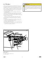
The product described operates automatically. However it is recom-
mended that you regularly verify that the lubricant is correctly trans-
ported along the lines.
The level of lubricant in the reservoir, if present, must be checked
visually at regular intervals. When the lubricant level is low, fill up
with lubricant, as described in chapter Filling with lubricant.
CAUTION
Always respect the equipment manufacturer's recommen-
dations concerning which lubricant to use.
CAUTION
Only use a clean lubricant. Soiled lubricants can cause
major defects in the system.
Different lubricants must not be mixed together. Doing so
can cause damage and require extensive cleaning of the
lubrication system. To prevent any risk of error, it is recom-
mended to clearly identify the lubricant used on the
reservoir.
Depending on the nature of the lubricant used, the user
should wear protective equipment such as glasses, a mask
and gloves. For further information please consult the tech-
nical file and the safety data sheet for the lubricant used.
7.2 Control Unit
The UCDE central unit features an integrated command and control
unit. The main function of this unit is to trigger a lubrication pulse
upon reception of a signal from the proximity sensor placed on the
chain to be lubricated.
Table 6
Buttons on the control unit
Button
Description
Manual start of the lubrication / stop of the lubrication in
progress
Navigation or increment
Navigation or decrement
Validation / access to a parameter for modification (press
ca. 5 s)
7.2.2 Control unit menus
The control unit software has seven main menus. These menus are
numbered for easy identification.
1
Display: real-time display of the lubrication status
2
Lubrication: configuration of lubrication mode (cyclic, semi-auto-
matic or continuous) and cycle time in case of cyclic lubrication
(modifiable by the user).
3
Number of axes: configuration of number of axes to be lubricated
on the chain for each lubrication cycle (changeable by the user)
4
Pitch jump: lubrication frequency according to lubrication points
5
Pump control: pump control setting
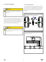
7.2.1 Interface
The command and control unit features an easy-to-use interface in
front of the UCDE unit housing
(† fig. 16)
.
This interface includes:
• a 2 × 16 digit screen
• four buttons
(† Table 6)
• a LED (default)
Fig. 16
User interface
24
Summary of Contents for SKF CLK
Page 37: ...37 ...


