


3 Design and function
3.1 General
CLK lubrication systems have a central unit and all electrical and
hydraulic components necessary to operate a lubrication system by
airless oil projection. The central unit comprises a housing with an
electromagnetic pump and an integrated control unit and a reservoir.
Their compact design makes it very easy to implement the CLK lubri-
cation systems as close as possible to the lubrication points located
on a moving chain.
3.2 Versions
The CLK lubrication system can be sold as a kit, mainly containing:
• the CLK central unit
• the projection nozzles
• the inductive proximity sensor
• the lubricant lines
• etc.
The table 1 gives an overview of the several existing kits
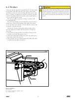
3.3 Construction
3.3.1 Central unit
The central unit
(† fig. 1)
is a compact group comprising a reservoir
mounted on a pump housing.
The pump housing houses an electromagnetic pump and an inte-
grated control unit. The control unit can be controlled and monitored
from the control panel located on the housing front side. For more
information on the control unit, refer to the section 6.2 Control unit.
The unit electrical connections are located under the rear part of
the housing. It comprises three connectors (power supply, proximity
sensor and fault outputs). A fourth connector can be optionally added
to check the lubricant level.
The hydraulic outlets (lubricant) are located on the housing side.
The reservoir, with a usable capacity of 7.5 l, is made of
translucent plastic to facilitate the control of the lubricant level.
Four mounting plates, placed on the reservoir rear side (×2) and
on the pump housing rear side (×2) allow the easy mounting of the
central unit against a wall or the machine wall.
3.3.2 Lubrication system kits
The complete kit of the CLK lubrication system includes, in addition
to the central unit, different accessory subsets:
• long pipe
• short pipe
• nozzles
• inductive proximity sensor
Table 1
Order information, oil lubrication system
Central unit
Nozzle
1)
Proximity switch
1)
Tube
1)
Kit No.
Flow rate
Outlets
Single
Double
Ø
Temperature
Range
short
long
CLK-460R-100+XXX
2)
60
4
–
4
12
-40 to +85 °C
7 mm
1
1
CLK-260R-100+XXX
2)
60
2
–
2
12
-40 to +85 °C
7 mm
1
–
CLK-460R-110+XXX
2)
60
4
–
4
18
–20 to +180 °C
8 mm
1
1
CLK-430R-101+XXX
2)
30
4
4
–
12
-40 to +85 °C
7 mm
1
1
CLK-430R-121+XXX
2)
30
4
4
–
2
-40 to +85 °C
4 mm
1
1
*) For more information on subsets, see technical data
2) The order number has to be completed with the voltage key of the central unit:
428
for 230 V AC, 50/60 Hz and
429
for 115 V AC, 50/60 Hz
10
Summary of Contents for SKF CLK
Page 37: ...37 ...


