


6.3.2.2 Nozzle mounting
To mount the projection nozzles, you can use the support provided
for this purpose
(† fig. 10)
. Once the support is mounted, it is only
possible to adjust horizontally the projection nozzle position. SKF
recommends therefore to simulate the nozzle positioning with res-
pect to the chain before mounting the support.
1
Install and mount the support. Depending on the chain configura-
tion, the support can be mounted in two different ways
(† fig. 11)
.
2
Place and secure the nozzles bracket (three possible positions)
(† fig. 10)
. Observe the distances
3
Insert the nozzles in the bracket slot from below
4
Insert and slightly tighten the washer and the nut
5
Adjust the nozzle position by sliding them along the slot
6
Tighten the nut
CAUTION
The chain to be lubricated is moving during the process. It is
therefore important to follow the installation distances to
avoid any mechanical damage to the projection nozzles.
1
2
3
4
5
6
Fig. 10
Proximity sensor and sensor support
Fig. 11
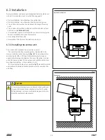
6.3.3 Mounting the proximity sensor
The proximity sensor is mounted on the same support as the
nozzles. SKF recommends to place the proximity sensor before the
projection nozzle relative to the chain travel direction.
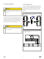
1
Mount the sensor on the bracket with the nut and the lock nut
2
Mount the bracket on the support
3
Adjust the sensor horizontal and vertical position
(† fig. 12)
. It
must be vertical with respect to a lubrication point
4
Observe the rated range of the sensor
(† Technical data)
CAUTION
It is necessary to observe the installation distances of the
proximity sensor.
P
n × P
n = 1 ; 2 ; 3 ; ...
n = 1
n = 2
≈ 2
– 6 mm
Fig. 12
Proximity switch distance
20
Summary of Contents for SKF CLK
Page 37: ...37 ...


