


6.3.2 Nozzle installation
The nozzles should be placed directly above the chain rollers, at the
starting point of the chain return belt
(† fig. 5)
. The projection head
should be placed vertically with respect to the lubrication point - i.e.
the friction zone between two roller elements,
(† fig. 8)
. In the case
where the two projection heads of the nozzle are not perfectly
aligned, it is possible to adjust the gap between them.
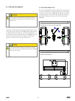
6.3.2.1 Nozzle adjustment
The center distance between the two spay heads of a nozzle is min
4.5 mm and max 10 mm. The nozzle heads should be perfectly ver-
tical to the lubrication points
(† fig. 9)
. Depending on the chain rol-
ler configuration, you can adjust mechanically the center distance
between the nozzle heads by means of a 2,5 mm Allen wrench
(† fig. 8)
.
2,5 mm
Fig. 8
Adjusting the center distance of the nozzle heads
220
24
Ø8 max.
0,5 – 5 cm
125
Fig. 9
Nozzles and nozzle support
CAUTION
Only remove the protections from the projection nozzle
heads at the last moment to avoid any damage due to ins-
tallation work.
CAUTION
The projection nozzles should be perfectly vertical to the
chain rollers. It is also mandatory to observe the installation
distances of the nozzles.
19
Summary of Contents for SKF CLK
Page 37: ...37 ...


