


1
2
3
PE
L1
L2
{ + }
{ -}
~
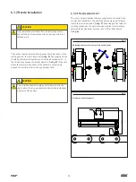
Table 3
Power supply connector pins
Pin
Description
1
L – phase
2
N – neutral
GND
GND – grounding
Table 4
Default output connector pins
Pin
Description
1
NO – closing contact
2
NC – opening contact
3
common
Table 5
Proximity switch connector pins
Pin
Description Wire color
1
24 V
brown
2
0 V
blue
3
Signal
black
1
2
3
1
2
3
24 V
SIGNAL
0 V
23
Summary of Contents for SKF CLK
Page 37: ...37 ...


