


38
37
158
127
5°
43,8
24
18
47,7
2 × Ø 8,5
60,8
206,2
81,8
220
=
=
2 × AC-A-420
198
=
=
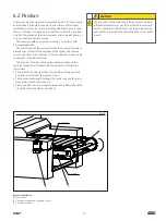
Fig. 2
Projection nozzles with proximity sensor mounted on a support
40,5
Ø15
59,5
Ø18
4,5 ... 10
Ø4
Ø4
SW 10
SW 13
SW 14
SW 10
SW 13
SW 10
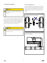
Fig. 3
Projection nozzles
Connector M12 (with 5 m cable)
Inductive proximity sensor
3 mounting positions
12
Summary of Contents for SKF CLK
Page 37: ...37 ...


