background image

LINC-CUT

®

 S 1020w-1530w

66

Lincoln Electric France S.A.S.

Avenue Franklin Roosevelt 76120 Le Grand Quevilly

76121 Le Grand Quevilly Cedex

www.lincolnelectriceurope.com

PERSONAL NOTES

Summary of Contents for LINC-CUT AS-CM-LCS1020WF125

Page 1: ... SAFETY INSTRUCTIONS FOR OPERATING AND MAINTENANCE MACHINE No MACHINE No AS CM LCS1020WF125 AS CM LCS1530WF125 AS CM LCS1020WF125 AS CM LCS1530WF125 AS CM LCS1020WTH80 AS CM LCS1530WTH80 AS CM LCS1020WTH80 AS CM LCS1530WTH80 Instruction manual ISSUE EN REF 8695 4795 REVISION E DATE 05 2022 Original instructions ...

Page 2: ...are in accordance with applicable European directives Please refer to the CE declaration enclosed to identify the directives applicable to it The manufacturer shall not be liable for any combination of parts not recommended by it For your safety please follow the non limitative list of recommendations and obligations a large part of which are included in the Labour Code Please inform your supplier...

Page 3: ...s and parameters of the FLEXCUTTM 125 CE plasma 14 Main specifications of the FLEXCUTTM 125 CE plasma power source 15 Main specifications of the LC125M torch 15 Equipment performance 15 Use of consumables of the FLEXCUTTM 125 CE plasma 15 80A plasma process TOMAHAWK 1538 LC100M torch 16 Controls and parameters of the TOMAHAWK 1538 plasma unit 16 Main specifications of the TOMAHAWK 1538 plasma powe...

Page 4: ... Customer Assistance Policy 64 PERSONAL NOTES 66 INFORMATION REVISIONS DISPLAYS AND PRESSURE GAUGES Measurement instruments or displays of voltage intensity speed accuracy etc are to be considered as indicators whether they are analogue or digital REVISION A 04 20 DATE DESCRIPTION PAGE Created All REVISION B 06 20 DATE DESCRIPTION PAGE Revision of safety instructions 6 REVISION C 04 21 DATE DESCRI...

Page 5: ...h with air renewal 2 Use must be limited to two hours of effective cutting per day average observed cutting time A touch screen and an intuitive user interface with a library of integrated shapes will allow you to start cutting at once A software suite is supplied to work with your programs which can be loaded from a USB drive The machine is easy to use and maintain and is guaranteed for two years...

Page 6: ... included in telephone technical support Email Lincoln Electric will reply to email sent to the address EU AutomationServices LincolnElectric com within 24 hours from Monday to Friday Training in LINC CUT S 1020w 1530w Lincoln Electric offers several training packages either in the customer s premises or in our Excellence Centre in Pont Sainte Maxence Please call 0825 132 132 for more details Linc...

Page 7: ... in place in its operating position Do not lift the machine from the cable drag chain or cable carrier side Once the machine is in position level the table with the adjustable feet Start with the four corner feet and end with the two central feet only on LINC CUT S 1530w Make sure that the table does not rock Qty Description Part number 1 LINC CUT S 1530w machine with FLEXCUTTM 125 CE plasma cutti...

Page 8: ...ng devices must be removed before using the machine DO NOT PUT BACK the bolts after removing the locking devices as that will lead to permanent damage to the gantry Do not lift the machine from the cable drag chain or cable carrier side Putting in place the LINC CUT S 1020w 1150 mm mini 650 daN 650 daN ...

Page 9: ...vices must be removed before using the machine DO NOT PUT BACK the bolts after removing the locking devices as that will lead to permanent damage to the gantry Do not lift the machine from the cable drag chain or cable carrier side Putting in place the LINC CUT S 1530w 1150 mm mini 850 daN 850 daN ...

Page 10: ...tructions Protect yourself and others from the risk of serious injury or death Keep children away If you use a pacemaker please seek the advice of your physician before using the machine Make sure that all installation operation maintenance and repair procedures are carried out by qualified personnel only Handling conditions For installation or maintenance operations the operator must use an appro...

Page 11: ...to be provided by the customer The customer must therefore take protective measures appropriate for the equipment for handling the workpieces IMPORTANT While handling sheets to cut take the necessary precautions to avoid im pacts on the machine and the rolling tracks Impacts on any of the elements can lead to squareness faults or the malfunctioning of the electrical shaft and therefore incorrect c...

Page 12: ...ate m h required to not exceed the short term 15 minutes exposure limit value for NO2 6 mg m 420 170 0 0 Fresh air inflow rate m h required to not exceed the occupational eight hours exposure limit value for NO2 6 mg m 3300 3270 3240 3200 Note 1 The concentration stated indicates the average value in the area In reality it is higher close to the table The quantity of residual fumes emitted depends...

Page 13: ...e placed on a stable floor of the industrial type as an example Single piece concrete slab made at least 21 days previously BAEL 93 standard 200 mm thick The thickness of the slab and its reinforcement are provided for guidance and must be adapted to the characteristics of the floor OR Concrete longitudinal members in one piece 20 Mpa 350 kg m concrete with metal reinforcement Flatness over the en...

Page 14: ...260 litres Height between bottom of beam and top of table 127 mm Thickness capacity of the table 20 mm with 1000x2000 mm plate 25 mm on half the surface Engines step 2 8 Nm Reduction drive 3 1 belt reduction drives Clutch with pre loaded springs Guides and drive Longitudinal guides with 20 mm bearing pads and racks Transverse guides with 15 mm bearing pads and racks Recommended service time 4 hour...

Page 15: ...capacity 495 litres Height between bottom of beam and top of table 127 mm Thickness capacity of the table 20 mm with 1500x3000 mm plate 25 mm on half the surface Engines step 2 8 Nm Reduction drive 3 1 belt reduction drives Clutch with pre loaded springs Guides and drive Longitudinal guides with 20 mm bearing pads and racks Transverse guides with 15 mm bearing pads and racks Recommended service ti...

Page 16: ...arth cables of the table at the front of the machine The earth rod is not supplied with the machine Options Marker See Marker installation and configuration section Please refer to the instruction manual of the FLEXCUTTM 125 CE or TOMAHAWK 1538 for complete instructions for installation and operation Only a qualified electrician may connect the input leads to the LINC CUT S 1020w 1530w and the FLE...

Page 17: ...f Plateguard Red and water for the remaining volume Supply by the customer of two power supplies earth Machine 0 75 Kw 0 9 kVA 4A 220 230 V 2P E 230V 16A single phase female wall connector Power source FLEXCUTTM 125 CE 22 Kw 28 kVA 40A 400 V 3P E 400V 63A three phase female wall connector Building earth 5 Ohms max FLEXCUTTM 125 CE 15 6 m3 h 7 2 bar Hose connector Ø 10 WARNING The quality of the ai...

Page 18: ...operating manual of your FLEXCUTTM 125 CE supplied with the plasma cutting unit When the machine is on and the automatic test is executed all the indicators light up on the control panel Rear controls 9 10 12 11 13 9 Air or gas inlet 1 4 6 35 mm NPT quick connect 10 Access to reconnection panel 11 Input cable tie 12 14 pin CNC interface 13 Fan 125A plasma process FLEXCUTTM 125 CE LC125M torch Cont...

Page 19: ...ctor Universal central connector Equipment performance Materials Carbon steels stainless steels Mid plate thickness up to 25 mm steel Angular cutting quality Range 4 5 according to ISO9013 Life of consumables 350 cutting cycles 20 sec at 125 A and 750 cycles at 105 A Processes switchable with no change of consumables Compressed air 6 5 bars 260 l min cooling and cutting gas Consumables starter pac...

Page 20: ...Work cable connection 11 CNC interface Front controls Please refer to the operating manual of your TOMAHAWK 1538 supplied with the plasma cutting unit When the machine is on and the automatic test is executed all the indicators light up on the control panel 80A plasma process TOMAHAWK 1538 LC100M torch Rear controls 12 13 15 14 12 Air inlet 13 Fan 14 Power supply cable 15 On Off switch 7 6 9 8 10 ...

Page 21: ...pply cable and fuses Fuse slow blow or circuit breaker D characteristic Power cable 32 A 4 x 4 mm Dimensions Height Width Length Weight 455 mm 301 mm 640 mm 34 kg Operating temperature 10C to 40 C Storage temperature 25C to 55 C Main specifications of LC100M torch Striking Contact without HF Bundle length 7 5 metres Connector Universal central connector Performance of the TOMAHAWK 1538 LC100M torc...

Page 22: ...tion to the LC100M automatic torch your TOMAHAWK 1538 installation is supplied with the LC105 manual torch That torch may be used occasionally possibly for skeleton cutting Its use is simple but requires some precautions Switch off the TOMAHAWK 1538 Remove the external control cable from the machine Remove the connector of the LC100M torch Connect the connector of the LC105 torch Check that the co...

Page 23: ...ill move to the bottom left corner of the table its Home position Your machine is now ready to operate To start up the LINC CUT S 1020w 1530w CNC machine please follow the instructions below The complete user guide is available as an embedded file in VMD Use the button with the question mark to access the file 1 2 3 Bottom left corner Starting up the LINC CUT S 1020w 1530w Step 1 Step 2 Step 3 Shu...

Page 24: ...em Apply the machine emergency stop Step 1 Step 2 Step 3 Swipe your finger on the screen starting from the left hand edge up to the centre Press the Windows button Step 4 Press Shutdown Step 5 Switch off the power supply to the machine To switch on the machine Switch on the power supply to the machine Step 7 Step 8 Step 9 If shuttle PC with On Off button press the On button of the PC If metal PC t...

Page 25: ...plays the job setup job graph job g code or a chart of tool holder movements 3 Datum Program Zero Establishes the machine zero through DATUM along with the program zero on the machine 4 Cut Parameters AVHC Settings for the height control and it s functions 5 Run group These buttons control job starting and stopping 6 Jogging Controls the torch movement on the machine with the program run speed 7 D...

Page 26: ...you to create a user defined shape based on 27 common parts See the USING THE SHAPE LIBRARY section for details Project configuration In PLATE SETUP you can make alterations to the job itself ROW AND COLUMN Allows you to add multiples by adding numbers to generate a GRID ARRAY of the job you have selected TRANSFORMS Allows you to MIRROR ROTATE or SCALE your job MATERIAL SENSING This function works...

Page 27: ...ected OPERATOR means a standard user with a standard interface PRODUCTION OPERATOR means a standard user with a simpli fied interface TECH SUPPORT is only used by technical support staff password protected Shutdown SHUTDOWN allows you to shut down VMD and the computer This is to be used when you want to shut down the computer The TURN OFF ACCUMOVE CONTROLLER popup window is displayed Press the eme...

Page 28: ... Height is the distance at which the torch will retract from the material to strike a pilot arc before moving to the piercing height Pierce Height is the distance at which the head is positioned above the material during piercing Cut Height is the distance between the tip of the torch and the top of the material during cutting Pierce Delay is the time during which the torch pierces the material be...

Page 29: ...ize Viewport will display all the views on a single screen Graphics View MACHINE LIMITS is used to display the machine limits in blue The head position is represented by crossed white lines The paths assigned to the plasma tool are displayed in red The paths assigned to the pneumatic marker are displayed in green Rapid trav els are represented by a dotted grey line Zoom to Machine makes it possibl...

Page 30: ...ut Active Run Dry Run This button switches between the ACTIVE RUN and DRY RUN modes ACTIVE RUN This will activate your torch to fire when you RUN a job DRY RUN This will deactivate your torch In DRY RUN mode the torch will simulate all the movements without activating the torch Run Job RUN JOB will start the job that is loaded into the VMD Stop STOP button will stop the machine during any movement...

Page 31: ...eed to obtain the best possible cutting quality Continuous makes it possible to move the torch as long as a finger is pressing the arrow Incremental Jog Pressing in a direction moves the torch in the same direction while using the increment distance adjustment bar to modify the distance The adjustment bar allows you to use increments from 0 000 and 0 100 You can directly enter any number in the di...

Page 32: ... Defined You can enter the cutting parameters manually based on the cut charts provided in the FLEXCUTTM 125 CE or TOMAHAWK 1538 manual Sample Voltage is an On Off switch On with MODE AUTO At the beginning of the cut the controller learns the proper Arc Voltage and maintains the desired Cut Height value entered in CUT PARAMETERS Off with MODE AUTO The AVHC will adjust based on the SET VOLTAGE and ...

Page 33: ...ing its zero point Dashboard The dashboard displays the indicators and tools of the host for the operator Arc Voltage displays the plasma arc voltage return during cutting Plasma Pierce Count This counter is used for keeping a trail of the number of piercing operations carried out by plasma consumables Counter to reset with each change of consumable Process Displays the cutting process under way F...

Page 34: ...h the laser activated How the Laser Works The laser is positioned with a slight angle in relation to the torch so that it passes directly under its median line With the torch correctly positioned on the machine and the plate thickness entered in the system the Z axis will adjust the position when it is activated so that the projected point is on the plate surface under the central line of the torc...

Page 35: ... Plasma plate marker or oxy Lead In Radius allows you to create the lead in radius If a line lead in is necessary set this to 0 Lead In is the length of the pierce point movement on the tool path This is usually 0 12 Lead Out is the length of the cut created outside the cut path This must be 0 if you are using plasma Overburn is the length measured after the end start point Used with thicker mater...

Page 36: ...saved it in the JOBS folder you will need to press BROWSE and locate your job IS THE JOB KERF COMPENSATED The parts in the SHAPE LIBRARY are not suitable for KERF COMPENSATION Select NO and that will add the kerf depending on the thickness of the material of the piece For VMD Nest and TMCAD programmed tasks select YES Once selected press ON The job is displayed on the GRAPHICS screen ...

Page 37: ...CH DRIVES ON Press HIDE and then in the lower left corner press DATUM The Torch will travel to the limits of the machine and establish the MACHINE ZERO Open a job Once the MACHINE ZERO has been established it is time to open a job and get it prepared to cut Press SELECT JOB and locate your file Set up the process In the PROCESS SETUP tab enter the material thickness and the amperage to be used for...

Page 38: ...Press RUN JOB That will simulate the loaded program without activating the plasma torch If you are satisfied with the dry run and machine movements switch from the DRY RUN to the ACTIVE RUN mode to start the cut according to the loaded program Press RUN JOB If you believe the machine is moving too fast for the material you can modify the feed speed using the FEED RATE OVERRIDE scroll bar By defaul...

Page 39: ...RIDE at 100 the first line cuts at 4 3 m min and drops 10 ipm each line until the last line set at 80 ipm and the outside perimeter is 100 ipm If the FEED RATE OVERRIDE set to 50 the lines would range from 85 to 40 with the outside at 50 Check the amperage and thickness of material in the cut chart Change the PROGRAM FEEDRATE OVERRIDE if you need a higher or lower feed rate to suit the material th...

Page 40: ...UT S 1020w 1530w 36 Develop your own cut chart Material Thickness Type Amperage Cut speed Pierce delay Pierce height Cut height Use this template to create your own custom cut charts using the line speed test ...

Page 41: ...icking the NESTING button and NESTED JOB LIST will be displayed on the screen To start a new nest press NESTED JOBS Select NEW NESTED JOB and the ADD NESTED JOB dialogue box opens In this dialogue box enter a name for your nest in NESTED JOB NAME This will become the file name of your job The dialogue boxes below offer pull down lists Find the thickness of the material you plan to cut along with t...

Page 42: ...e default VMD folder is in C ControllerData Jobs The two check boxes VERIFY and ARTWORK VERIFY will display the pieces to examine layers and other details about the individual parts ARTWORK will change the tool paths to an ONLINE tool path and bypass the kerf adjustments On the right you will see the JOB PROPERTIES that can be applied to your parts IMPORTING PROPERTIES includes basic changes to th...

Page 43: ...part then select COMPLETE NEST in the right hand toolbar This will open the CREATE JOB dialogue box Enter the location where you want to save the job and check the amperage you are using Then press OK OpenNestinVMD In the NEST screen at the bottom left press BACK RUN which will take you back to the VMD RUN screen From now on to run your nest go to SELECT JOB and locate your file In the AVHC tab sw...

Page 44: ...has started Visual Machine Designer will start automatically 3 Press DATUM to establish the machine zero point 4 In the PROCESS SETUP tab enter the plate thickness 5 mm and the appropriate amperage of the plasma consumables FLEXCUTTM 125 CE 65amp That will load the cutting parameters with the appropriate parameters depending on the cut charts 5 Press SELECT JOB 6 Locate the file 1530W 65A 5mm_V1 g...

Page 45: ...ll find that a larger orifice or an irregularly shaped hole will be the telltale signs of excessive wear The electrode pay close attention to the amount of hafnium left in the tip The larger the crater in the electrode tip the more the electrode is worn Replace the electrode if the centre pit depth is greater than 0 06 1 5 mm Also see if there are dark swirl marks near the tip of the electrode Alt...

Page 46: ...orch impact safety system Machine Move the machine to the reference position and separate the torch support by pulling the torch down to the left or right The rear plate must now be visible Using a cloth remove any metal debris from the two magnets or the three positioning notches To assemble the torch first line up the upper edges of the torch support and slowly put the torch back in its idle pos...

Page 47: ...e bottom of the keyhole and tighten the bolts to 2Nm Step 6 Repeat steps 1 to 5 on the other side of the table Step 7 Remove the red side covers of the gantry by removing the 3 175 mm hex head bolts on each cover Step 8 Once the covers are removed the grease fittings are visible Fix the grease gun and pump until the grease comes out through the pocket where the bolt and spring enter the assembly S...

Page 48: ...n the plates over to lengthen their life Water pan The water in the pan must be emptied and the pan cleaned every 2 to 4 months There is a plumbing valve 12 7 mm at the rear left of the table To dispose of the water please contact your local environmental or water authorities After draining the water remove all pieces of metal and dispose of them in accordance with national and local regulations C...

Page 49: ...e and is the cut that delivers the best bevel Basically the best bevel is to the right of the direction of travel Conventional Climb Corners may show more bevel than normal cuts That happens when the machine slows down for the direction change In some cases a lower amperage allows slower travel speeds and reduces the slowdown bevel at corners Sharp corners can be achieved by cutting a larger shape...

Page 50: ... height Torch too low Equal bevel on all sides Minimum bevel Longer consumable life Unequal bevel One side may be straight and the other excessively bevelled May be caused by a worn tip Excessive bevel The cut may not go all the way through the material Reversed bevel The torch may touch the material and short out or damage the tip Position of torch while cutting Bevel of finished part ...

Page 51: ...de when they touch the material which prevents the cut from going through the material When the machine begins to move before a pierce is completed the cut will not be complete In such a case the dwell time or pierce delay must be adjusted to allow for enough time to pierce the material When a path of the cut does not return to the starting point there may be mechanical slipping or binding In some...

Page 52: ...matic lubricator is not filled with oil for pneumatic tools before shipment Fill the pneumatic tool with oil before use Air pressure regulator Molex connector Pneumatic oiler Lower tee fitting Assembly holes Intensity setting indi cator Stylus Unpacking Take the plate marker out of the packaging and check the contents Assembled marker Pneumatic connection assembly Pneumatic oil approximately 0 12 ...

Page 53: ...with the 4 screws use thread sealant You should start fastening the marker from the bottom right corner Connect the pneumatic supply to the tee connector Locate the Molex 2x2 cable at the exit of the cable drag chain Connect the cable in the connector till it clicks in place Careful The connector can only be inserted in one way Do not apply force on the connector When it is correctly lined up the ...

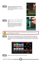
Page 54: ... to the machine air inlet Step 6 Air supply of FLEXCUTTM 125 CE or TOMAHAWK 1538 Insert HERE Air supply Accumove The grey pipe is located in the pocket above the Accumove Connect the air pipes Step 7 Switch on the air compressor and check that there is no air leak The air pressure may not exceed 8 3 bar Step 8 Adjust the marker regulator with pressure between 0 34 and 0 69 bar That pressure must b...

Page 55: ... activation button Step 12 Enable and disable the marker 3 to 4 times to make sure that the marker is operating correctly Set the appropriate movement and speed using the regulator Step 13 Define the parameters of the FLEXCUTTM 125 CE or TOMAHAWK 1538 and machine to suit the material used Move the torch on the plate and click on Set Program Zero That will put the LINC CUT S 1020w 1530w into the ma...

Page 56: ...he scrolling keys adjust till the stylus drops into the hole Step 16 In incremental mode the machine will move the gantry at a definite incremental pitch every time the scrolling keys are pressed Once the tip of the stylus has fallen into the hole click the Set Offset button located in the row of markers That will automatically define the offset between the marker and the body of the plasma torch ...

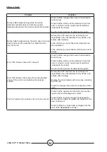
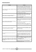
Page 57: ...on as ADMIN Reload your configuration Press OK Run the machine DATUM If that does not solve the problem contact Customer Support The beam binds while working on parts Lubricate the rail glides If that does not solve the problem contact Customer Support Cuts are not coming out square or degraded cut quality Check the plasma torch consumables and also the settings in the cut chart Check that the tor...

Page 58: ...HS mode is set to Always Error IHS Failure Check VFC Ground Check that the orange ohmic wire is connected to the torch lug Check that the surface of the material is free from rust or corrosion which could prevent electrical contact with the shield See the ohmic detection troubleshooting guide Error IHS Failure Clear dross from consumables error with the torch not contacting the material surface Re...

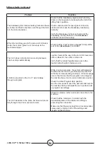
Page 59: ...oltage mode is set to ON Check the connection of the arc voltage measurement cable between the VFC box and the plasma source The torch traces the part out but does not fire Check that the Dry Run Active Run button shows Active Run Check that OK to Move is enabled in the machine control panel If the OK to Move option is disabled check the errors indicated on the plasma source The VMD screen display...

Page 60: ...l and click on Reset Z then click on Run Job Verify that the retract height value is set to the desired retract height in between cuts A limit is exceeded on the X or Y axis midway through a program While running a program the system will determine whether the next line of g code keeps the machine within its normal operating envelope If this message occurs that means that the program is too large ...

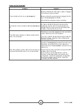
Page 61: ... The firmware currently uploaded into the controller is not the correct version for the software Log in as an Admin and load the firmware under the Machine Settings Advanced tab by following the onscreen instructions One of the machine motors does not move when you try to start the DATUM mode or move the machine Shut down the Accumove controller and make sure that all the connections of the motor ...

Page 62: ...ected and is yellow Reinstall the torch on the breakaway till the indicator is grey and shows Connected Check that the breakaway cable is in place in the unit itself and at the rear of the Accumove controller The Execution Error Overtravel Detected error oc curs when you click the Run Job button If operating near the limits of the machine reset the program zero and move the material further away f...

Page 63: ...eck that the pierce and cut height are set to the recommended values Check that the height control mode is set to Auto and not Manual Check that the Sample voltage function is set to ON Check for dross near the piercing points that may interfere with the torch sensing the plate The torch does not appear to maintain a consistent cut height with the material which warps Check that the height control...

Page 64: ...LINC CUT S 1020w 1530w 60 ...

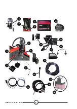
Page 65: ...ts of a machine or installation are referenced in the photographs and sketches The descriptive tables contain three types of item items normally held in stock 4 items not held in stock 8 articles upon request no reference For such parts please complete the list of parts page and send us a copy In the Order column state the number of parts required and indicate the type and number of your equipment...

Page 66: ...LINC CUT S 1020w 1530w 62 1 2 3 4 7 8 9 10 11 12 13 14 15 16 17 18 6 5 20 19 ...

Page 67: ...on the PC does not have a switch AS CS 103 0005 02 4 SHUTTLE PC depending on the version the PC has a switch 10 AS CS 07007331 4 HDMI cable 11 AS CS 400 0014 00 4 12 VDC PC power supply 12 AS CS 101 1100 05 4 Height regulation unit 13 AS CS 07007316 4 22 touch screen 14 AS CS 181 2015 00 4 Inductive sensor 15 TMS 181 2037 4 LINC CUT S 1020w octopus bundle AS CS 07007310 4 LINC CUT S 1530w octopus ...

Page 68: ... s particular purpose with respect to such information or advice As a matter of practical consideration we also cannot assume any responsibility for updating or correcting any such information or advice once it has been given nor does the provision of information or advice create expand or modify any warranty with respect to the sale of our products Lincoln Electric is a responsible manufacturer b...

Page 69: ...65 User s guide ...

Page 70: ...LINC CUT S 1020w 1530w 66 Lincoln Electric France S A S Avenue Franklin Roosevelt 76120 Le Grand Quevilly 76121 Le Grand Quevilly Cedex www lincolnelectriceurope com PERSONAL NOTES ...

Reviews: