Diagnostic aids
3-1
5025-2xx, 4xx
3. Diagnostic aids
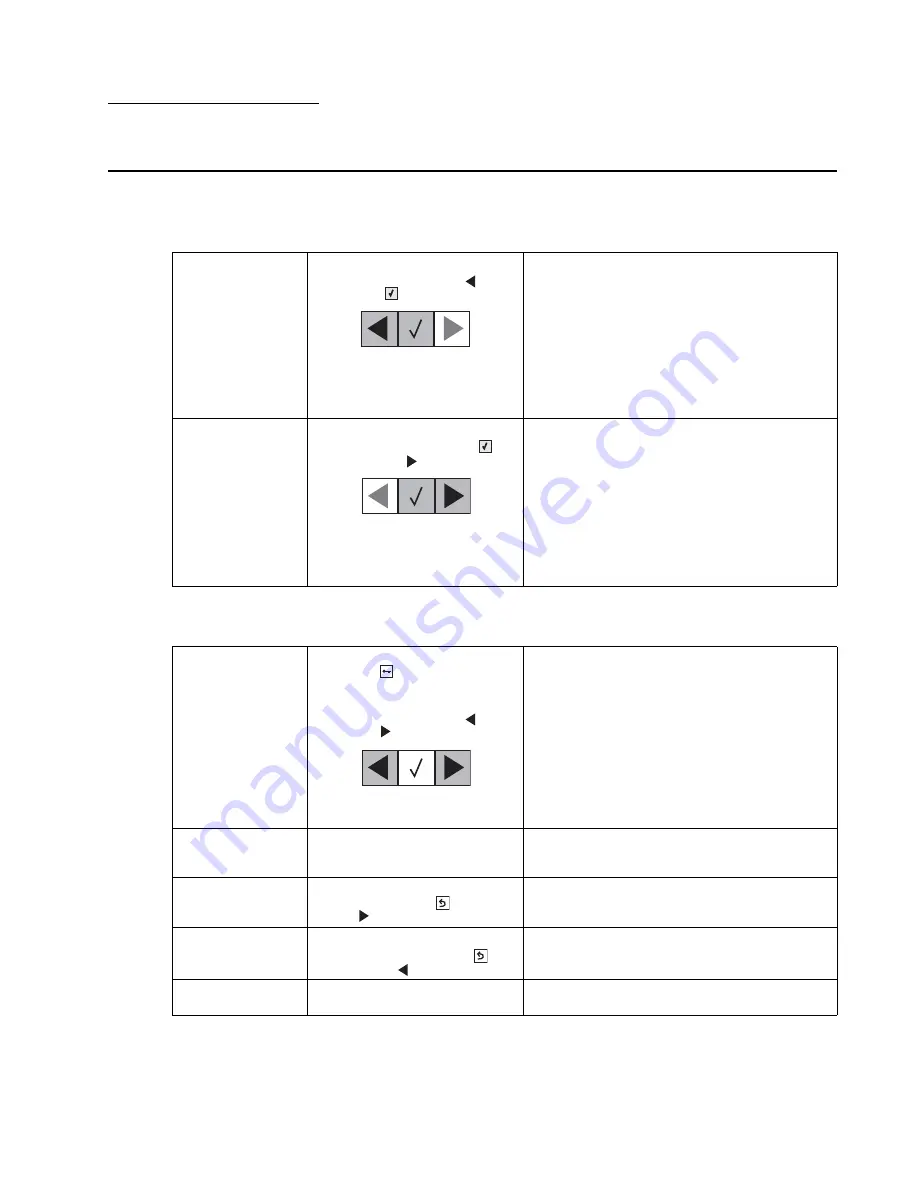
Accessing service menus
There are different test menus that can be accessed during POR to identify problems with the printer.
The following menus do not require a POR:
To run the printer diagnostic tests described in this chapter, you must put the printer in Diagnostics Menu or in
the Configuration Menu.
Diagnostics Menu
1. Turn the printer off.
2. Press and hold
Left
(
) and
Select
(
).
3. Turn the printer on.
4. Release the buttons when the
installed memory and
processor speed displays.
The Diagnostics menu group contains the settings
and operations used while manufacturing and
servicing the printer.
See
“Diagnostics Menu (Diag Menu)” on
page 3-2
for more information.
Configuration Menu
1. Turn the printer off.
2. Press and hold
Select
(
)
and
Right
(
).
3. Turn the printer on.
4. Release the buttons when the
installed memory and
processor speed displays.
The Configuration menu group contains a set of
menus, settings, and operations which are
infrequently required by a user. Generally, the
options made available in this menu group are
used to configure a printer for operation.
See
“Configuration menu (Config Menu)” on
page 3-24
for more information.
Network SE Menu
1. From the Ready prompt, press
Menu
(
).
2. Select Customer Network/
Ports menu.
3. Press and hold
Left
(
) and
Right
(
).
4. Release the buttons when the
menu appears.
SE Menu
In a browser, add
/se
to printer’s
IP address. For example,
http://
158.183.3.2/se
.
Enters the SE menus online.
Additional error
message
information
While the error displays on the
panel, press
Back
(
) and
Right
(
).
Access secondary debug information.
Invalid Engine Code
Mode
1. Turn the printer off.
2. Press and hold
Back
(
)
and
Left
(
).
This mode is used if the machine has invalid code
and needs the correct code loaded. After entering
this mode, the firmware code can be updated.
Firmware update
from USB
For use on machines with
operator panel USB port.
See
“Updating printer firmware” on page 3-28
.
Summary of Contents for C 540n
Page 8: ...viii Service Manual 5025 2xx 4xx...
Page 13: ...Notices and safety information xiii 10 2 2009 5025 2xx 4xx...
Page 14: ...xiv Service Manual 5025 2xx 4xx 10 2 2009...
Page 142: ...3 52 Service Manual 5025 2xx 4xx...
Page 224: ...4 82 Service Manual 5025 2xx 4xx...
Page 225: ...Connector locations 5 1 5025 2xx 4xx 5 Connector locations Locations...
Page 227: ...Connector locations 5 3 5025 2xx 4xx Connectors...
Page 236: ...5 12 Service Manual 5025 2xx 4xx High voltage power supply HVPS diagram...
Page 237: ...Connector locations 5 13 5025 2xx 4xx Low voltage power supply LVPS diagram...
Page 238: ...5 14 Service Manual 5025 2xx 4xx Toner meter cycle TMC card Wireless network card...
Page 240: ...6 2 Service Manual 5025 2xx 4xx...
Page 242: ...7 2 Service Manual 5025 2xx 4xx Assembly 1 Covers 4 3 1 10 6 5 8 7 2 9...
Page 244: ...7 4 Service Manual 5025 2xx 4xx Assembly 2 Frames 5 2 4 7 6 1 3 8 9 3 10...
Page 246: ...7 6 Service Manual 5025 2xx 4xx Assembly 3 Electronics 2 4 6A 5 1 6B 7 8 6C 3 9...
Page 248: ...7 8 Service Manual 5025 2xx 4xx Assembly 4 Cables...
Page 250: ...7 10 Service Manual 5025 2xx 4xx Assembly 5 Media drawers and trays 1 3 2 4 2...
Page 258: ...I 6 Service Manual 5025 2xx 4xx...
Page 262: ......


