


4-16
Service Manual
5060-XXX
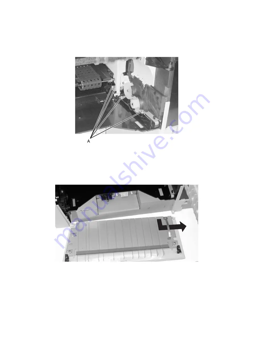
Fuser Drive Assembly
1.
Remove the
“Fuser” on page 4-15
.
2.
Remove the fuser drive assembly mounting screws (A) and remove the assembly.
Fuser Access Cover
1.
Open the fuser access cover.
2.
Carefully flex the fuser access cover to free the hinges from the mounting posts.
3.
Remove the fuser access cover.
Summary of Contents for 13P0150 - C 750dtn Color Laser Printer
Page 2: ... ii 6000 XXX ...
Page 4: ...5060 XXX ...
Page 10: ...viii 5060 XXX ...
Page 18: ...xiv Service Manual 5060 XXX ...
Page 120: ...2 100 Service Manual 5060 XXX ...
Page 199: ...Connector Locations 5 17 5060 XXX RIP Board ...
Page 203: ...Connector Locations 5 21 5060 XXX High Capacity 2000 Sheet Board ...
Page 205: ...Connector Locations 5 23 5060 XXX HVPS Board ...
Page 207: ...Connector Locations 5 25 5060 XXX HVPS Developer Board ...
Page 208: ...5 26 Service Manual 5060 XXX ...
Page 212: ...7 2 Service Manual 5060 XXX Assembly 1 Covers ...
Page 214: ...7 4 Service Manual 5060 XXX Assembly 1 1 Covers ...
Page 220: ...7 10 Service Manual 5060 XXX Assembly 5 Paper Feed Output Redrive ...
Page 222: ...7 12 Service Manual 5060 XXX Assembly 6 Multipurpose Feeder MPF ...
Page 224: ...7 14 Service Manual 5060 XXX Assembly 7 500 Sheet Integrated Tray ...
Page 228: ...7 18 Service Manual 5060 XXX Assembly 10 Cartridge Contact Assembly ...
Page 230: ...7 20 Service Manual 5060 XXX Assembly 11 Electronics ...
Page 232: ...7 22 Service Manual 5060 XXX Assembly 11 1 Electronics ...
Page 240: ...7 30 Service Manual 5060 XXX Assembly 12 Output Expander ...
Page 242: ...7 32 Service Manual 5060 XXX Assembly 12 1 Output Expander ...
Page 244: ...7 34 Service Manual 5060 XXX Assembly 13 5 Bin Mailbox ...
Page 246: ...7 36 Service Manual 5060 XXX Assembly 13 1 5 Bin Mailbox ...
Page 248: ...7 38 Service Manual 5060 XXX Assembly 14 500 Sheet Tray Option ...
Page 250: ...7 40 Service Manual 5060 XXX Assembly 14 1 500 Sheet Tray Option ...


