


Installation and Operational Instructions for ROBA
®
-twinstop
®
Type 8012._ _ _ _ _ Sizes 150 to 350
(B.8012.GB)
05/07/2010 TK/HW/SU
Chr. Mayr GmbH + Co. KG
Tel.: 08341 / 804-0
Eichenstraße 1
Fax: 08341 / 804-421
D-87665 Mauerstetten
http://www.mayr.de
Page 13 of 15
Germany eMail:
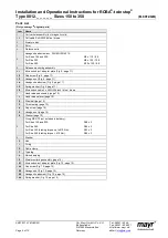
Electrical Connection for Operation
with Nominal Voltage (Without Overexcitation)
DC current is necessary for operation of the brake. The coil
voltage is indicated on the Type tag (14) as well as on the brake
body and is designed according to the DIN IEC 60038 (± 10 %
tolerance). Operation must take place via DC voltage with a low
ripple content, e.g. via a bridge rectifier or with another suitable
DC supply. Dependent on the brake equipment, the connection
possibilities can vary. Please follow the exact connections
according to the Wiring Diagram. The manufacturer and the user
must observe the applicable directives and standards (e.g. DIN
EN 60204-1 and DIN VDE 0580). Their observance must be
guaranteed and double-checked!
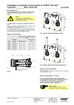
Earthing Connection
The brake is designed for Protection Class I. This protection
covers not only the basic insulation, but also the connection of
all conductive parts to the PE conductor on the fixed installation.
If the basic insulation fails, no contact voltage will remain.
Please carry out a standardized inspection of the PE conductor
connections to all contactable metal parts!
Supply Voltage Requirements
In order to minimise noise development of the released brake, it
must only be operated via DC current with low ripple content. AC
current operation can take place using a bridge rectifier or
another suitable DC power supply. Supplies whose output
voltages have a high ripple content (e.g. a half-wave rectifier, a
switch-mode mains adaptor, ...) are not suitable for operation of
the brake.
Device Fuses
To protect against damage from short circuits, please add
suitable device fuses to the mains cable.
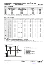
Switching Behaviour
The operational behaviour of a brake is to a large extent
dependent on the switching mode used. Furthermore, the
switching times are influenced by the temperature and the air
gap between the armature disk (2) and the coil carrier (1)
(dependent on the wear condition of the linings).
Magnetic Field Build-up
When the voltage is switched on, a magnetic field is built up in
the brake coil, which attracts the armature disk (2) to the coil
carrier (1) and releases the brake.
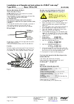
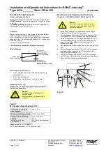
Magnetic Field Removal
AC-side Switching
The power circuit is interrupted
before the rectifier. The
magnetic field slowly reduces.
This delays the rise in braking
torque.
When switching times are not
important, please switch AC-
side, as no protective
measures are necessary for
coil and switching contacts.
Low-noise switching;
however, the brake engagement time
is longer (c. 6-10 times longer than with DC-side switching). Use
for non-critical brake times.
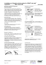
DC-side Switching
The power circuit is interrupted
between the rectifier and the
coil as well as mains-side. The
magnetic field reduces
extremely quickly. This causes
a quick rise in braking torque.
When switching DC-side, high
voltage peaks are produced in
the coil, which lead to wear on
the contacts from sparks and
to destruction of the insulation.
Short brake engagement times (e.g. for emergency
STOP);
however, louder switching noises.
Protective Circuit
When using DC-side switching, the coil must be protected by a
suitable protective circuit according to VDE 0580, which is
integrated in
mayr
®
rectifiers. To protect the switching contact
from consumption when using DC-side switching, additional
protective measures are necessary (e.g. series connection of
switching contacts). The switching contacts used should have a
minimum contact opening of 3 mm and should be suitable for
inductive load switching. Please make sure on selection that the
rated voltage and the rated operation current are sufficient.
Depending on the application, the switching contact can also be
protected by other protective circuits (e.g.
mayr
®
-spark
quenching unit), although this may of course then alter the
switching time.
1
2
3
4
5
6
230V~
max.
2,5A–
1/025.000.6
Brückengleichrichter
Bridge rectifier
IN
S
DC
OUT
[U– = 0,9×U~]
S1
F1
L
N
F1: external fuse
Coil
1
2
3
4
5
6
230V~
max.
2,5A–
1/025.000.6
Brückengleichrichter
Bridge rectifier
IN
S
DC
OUT
[U– = 0,9×U~]
S1
F1
L
N
F1: external fuse
Coil
Summary of Contents for E27 Series
Page 4: ...4 E27 Gearless Installation and maintenance 5323 en 2018 04 c...
Page 15: ......
Page 46: ...30 31 NOTES...
Page 109: ......
Page 110: ......
Page 111: ......


