Installation and Operational Instructions for ROBA
®
-twinstop
®
Type 8012._ _ _ _ _ Sizes 150 to 350
(B.8012.GB)
05/07/2010 TK/HW/SU
Chr. Mayr GmbH + Co. KG
Tel.: 08341 / 804-0
Eichenstraße 1
Fax: 08341 / 804-421
D-87665 Mauerstetten
http://www.mayr.de
Page 8 of 15
Germany eMail:
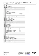
Design
The ROBA
®
-twinstop
®
is a spring applied, electromagnetically
releasing dual circuit brake.
It is used for installation in a gearless elevator and serves as a
brake assembly on the drive sheave shaft and as part of the
protective assembly against excessive upward-moving cage
speeds.
Function
ROBA
®
-twinstop
®
brakes are spring applied, electromagnetic
safety brakes.
Spring applied function:
In de-energised condition, thrust springs press against the
armature disks (2). The rotor (3) with the friction linings is
therefore held between the armature disks (2) and the machine
screw-on surface.
The motor shaft is braked by the rotor (3).
Electromagnetic:
Due to the magnetic force of the coils in the coil carriers (1), the
armature disk (2) is attracted against the spring force to the coil
carrier (1).
The brake is released and the shaft can rotate freely.
Safety brake function:
The ROBA
®
-twinstop
®
brakes reliably and safely in the event of
a power switch-off, a power failure or an emergency STOP.
State of Delivery
The brake body is partly assembled with armature disks (2),
distance bolts (4), adjusted microswitches (option, dependent on
Type) and hand release (Item 7 / option, dependent on Type).
The rotor (3), hexagon head screws (5), washers (9) and the hub
(10) with O-ring (11) are included loose in delivery.
Please check state of delivery!
Application
ROBA
®
-twinstop
®
for use as holding brakes with
occasional emergency STOP braking actions.
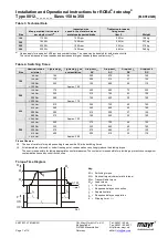
The max. permitted speeds and friction work, see
Table 3, must be observed.
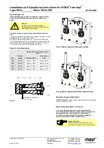
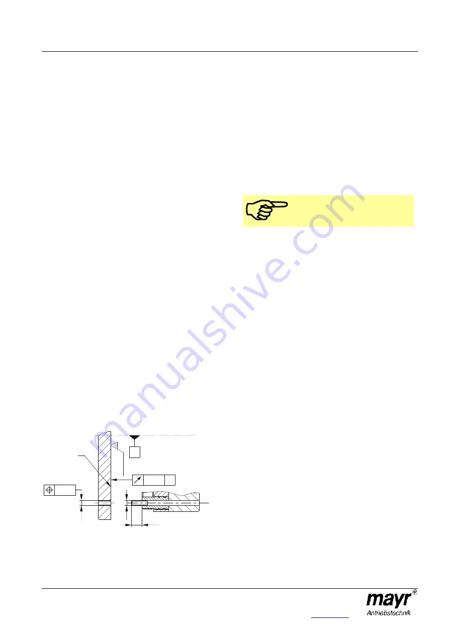
Fig. 5
Installation Conditions
The eccentricity of the shaft end in relation to the fixing
holes must not exceed 0,3 mm.
The position tolerance of the threaded holes for the
hexagon head screws (5) must not exceed 0,3 mm.
The axial run out deviation of the screw-on surface to the
shaft must not exceed the permitted axial run out tolerance
of
0,063 mm
in the area of the friction surface.
Measuring procedure acc. DIN 42955.
Larger deviations can lead to a drop in torque, to continuous
slipping on the rotor (3) and to overheating.
The toothed motor shaft (Type 8012._0_ _3) should be
designed according to the information given in the
applicable assembly drawing.
The O-ring groove must be inserted before the shaft is
splined. The O-ring groove must be free of burrs.
Please Observe!
The dimensions on the assembly drawings
are manufacturer-side recommendations.
On hub designs (Type 8012._1_ _3), the hub bore (10)
tolerances and the shaft must be selected so that the hub
toothing (10) is not widened. Widening of the toothing leads
to the rotor (3) jamming on the hub (10) and therefore to
brake malfunctions.
Recommended hub - shaft tolerance H7/k6.
If the hub (10) is heated for better joining, the O-ring (11)
must be removed beforehand and re-mounted after hub
installation.
The max. permitted joining temperature of 200 °C mu st not
be exceeded.
Dimensioning of the key connection according to the
requirements shaft diameter, transmittable torque and
operating conditions must be carried out. For this, the
corresponding user data must be known or the customer
must carry out the dimensioning according to the valid
calculation basis DIN 6892.
For the calculation, a hub quality of Re = 300 N/mm
2
should
be used.
The length of the key should lie over the entire hub (10).
For the dimensioning of the key connections, the permitted
tensions common in machine construction must be
considered.
The mounting dimensions and the screw-on surface s with
depth K + 2 mm (K = screw projection) acc. Catalogue or
applicable assembly drawing must be given (Fig. 5).
The rotor and brake surfaces must be oil and grease-free.
A suitable counter friction surface (steel or cast iron) must
be used. Sharp-edged interruptions on the friction surfaces
must be avoided. Recommended surface quality in the area
of the friction surface Ra = 1,6 µm.
In particular customer-side mounting surfaces made of
grey cast iron are to be rubbed down additionally with
fine sandpaper (grain
≈≈≈≈
200 – 400), or ideally with a
sander.
Please abstain from using cleaning agents containing
solvents, as they could affect the friction material.
During longer downtimes, we recommend the use of
suitable corrosion protection measures for the mounting
surface (e.g. zinc-phosphate coating) until initial operation.
0,063 A
A
Ra
1
,6
K
s
s
Ø 0,3
Mounting
surface
Motor shaft
centre axis
Summary of Contents for E27 Series
Page 4: ...4 E27 Gearless Installation and maintenance 5323 en 2018 04 c...
Page 15: ......
Page 46: ...30 31 NOTES...
Page 109: ......
Page 110: ......
Page 111: ......


