


Installation and Operational Instructions for ROBA
®
-twinstop
®
Type 8012._ _ _ _ _ Sizes 150 to 350
(B.8012.GB)
05/07/2010 TK/HW/SU
Chr. Mayr GmbH + Co. KG
Tel.: 08341 / 804-0
Eichenstraße 1
Fax: 08341 / 804-421
D-87665 Mauerstetten
http://www.mayr.de
Page 12 of 15
Germany eMail:
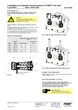
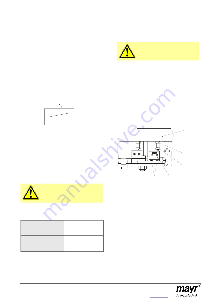
Wear Monitoring (15) Fig. 10
(Option, dependent on Type)
Only one microswitch for wear monitoring (15) is required per
ROBA
®
-twinstop
®
, which is mounted onto the brake as shown
in Fig. 10.
The
ROBA
®
-twinstop
®
brake is delivered with manufacturer-
side adjusted wear monitoring (15).
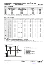
Function
Due to wear on the rotor, (3) the air gap "a" between the coil
carrier (1) and the armature disk increases (2).
Once the maximum air gap (limit air gap) of 0,9 mm has been
reached (Table 1), the microswitch contact (15.1) switches over
and emits a signal.
The rotor (3) must be replaced.
The customer is responsible for signal evaluation.
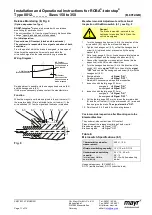
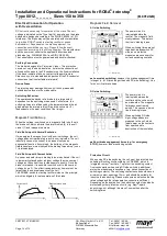
Wiring Diagram:
Before replacing the rotor (3)
•
Clean the brake and remove abraded particles using
compressed air.
•
Do not inhale brake dust.
•
Measure the rotor thickness "new" (see Table 2).
Replacing the rotor (3)
Replace the rotor by following the Brake Installation
instructions backwards.
Danger!
The drive brake must be load-free
on hoist drives.
Otherwise there is a danger of load
crashes!
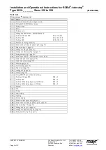
Table 7:
Microswitch Specifications (15.1)
Characteristic values for
measurement:
250 V~ / 3 A
Minimum switching capacity:
12 V, 10 mA DC-12
Recommended switching
capacity:
for maximum lifetime
and reliability
24 V, 10...50 mA
DC-12
DC-13 with free-wheeling
diode!
Usage category acc. IEC 60947-5-1:
DC-12 (resistance load), DC-13 (inductive load)
Manufacturer-side Adjustment and Functional
Inspection of the Microswitch (15.1), see Fig. 10
Danger!
The brake is mounted, secured to the
tightening torque (see Table 3) and the
coil is de-energised.
1. Connect the inspection or measurement device (diode
inspection) to the NC contact black/grey.
2. Turn the hexagon head screw (15.4) in the direction of the
microswitch (15.1) until it switches, and apply pre-tension
via the spring washer (15.5) using the hexagon nut (15.3).
3. Hold the hexagon nut (15.3) and turn the hexagon head
screw (15.4) back until the microswitch contact (15.1)
switches over again.
4. Mark the position of the hexagon head screw (15.4) (marker
pen).
5. Hold the hexagon head screw (15.3) and turn the hexagon
head screw (15.4) approx. 0,6 – 0,7 turns back in the
direction of the microswitch (15.1).
6. Counter the hexagon head screw (15.4) with the hexagon
nut (15.3) and mark the position using red securing lacquer.
7. Mount the Wear Monitoring guideline sign.
Fig. 10
1
6
15.2
15.1
15.4
15.3
15.5
2
1
4
2
NC Contact
Grey onnection
c
Connection when
wear limit is reached
NO Contact
blue connection
Connection when
wear limit is not yet reached
COM Contact
lack c
B
onnection
Summary of Contents for E27 Series
Page 4: ...4 E27 Gearless Installation and maintenance 5323 en 2018 04 c...
Page 15: ......
Page 46: ...30 31 NOTES...
Page 109: ......
Page 110: ......
Page 111: ......


