20 / 31
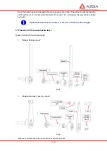
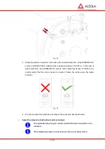
Fig. 24
In brakes that have optical detectors (
micro-switches
) mounted, on connecting/disconnecting the
brake the red LED of the detector must change status.
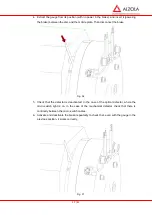
Fig. 25
Should any of the
micro-switches
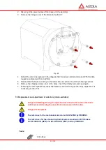
not behave in the way described above it may be necessary to
readjust or replace the detector. Consult point 7.2 “
Replacement and adjustment of detectors
(micro-switches)”.
Check that the detector is clean.
Check that the rubber dust-cover fits and prevents the insertion of particles or light (in the case of
optical
micro-switches
) in the detector.
Exposing of the microswitches to silicon gas may cause their dysfunction.
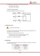
6.3 Winding verification:
Checking the resistance: Check that the resistance of the winding is correct. A reading below that
shown on the characteristics plate will be a sign that the winding has been damaged. In this case
it will be necessary to replace the brake as a whole. Consult the nominal value of the resistance
in section 1.5
“General characteristics”
.
7 SPARE PARTS:
Spare parts are considered to be those components that may be replaced in the installation of
the lift without prejudice to the safety of the brake.
7.1 Disc replacement:
21 / 31
Danger: the following process leads to releasing the brake, with the consequent
risk of uncontrolled movement of the lift cabin and the counterweight.
Danger of entrapment.
Carrying out this process may require prior withdrawal of the encoder and
subsequent assembly and readjustment.
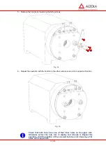
1. Once the installation has been secured, remove the plastic caps and position and tighten the
shipping screws, painted red, to avoid the brake dismantling.
Fig. 26
Fig. 27
Summary of Contents for E27 Series
Page 4: ...4 E27 Gearless Installation and maintenance 5323 en 2018 04 c...
Page 15: ......
Page 46: ...30 31 NOTES...
Page 109: ......
Page 110: ......
Page 111: ......


