


16 / 31
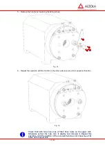
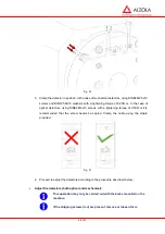
Check that, without using force, that it is possible to turn both handles
slightly (approximately 4 degrees).
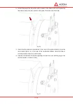
9- In the
manual release
levers, not in the
Bowden release
levers, tighten the DIN 912 M8x20
central fixing screw for both levers. (In the
Bowden
release
levers we recommend removing
the screws).
Fig. 19
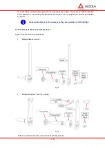
To simplify the manual lever assembly process, in circumstances where
this operation has to be repeated on numerous occasions, ALZOLA may
make special tooling available to facilitate this task.
4 ELECTRIC INSTALLATION
4.1 Before starting:
CAUTION: Danger of electrocution.
CAUTION: Danger of the lift falling.
CAUTION: Danger of causing irreparable damage to the brake.
4.2 Tools:
Screwdriver
17 / 31
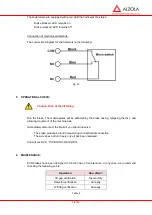
4.3 Brake connection:
EVO brakes are brakes that use direct current. Peaks in voltage must be
prevented from damaging the winders. Varistors capable of absorbing
voltage peaks must be placed in position.
Ensure that the Voltage in the grid is suited to the brake (consult the
characteristics label).
EVO brakes consist of two independent electric circuits. They must be connected according to the
following diagram:
Fig. 20
4.4 Detector connection (micro-switches):
Connecting the optical detectors:
An incorrect connection of the detectors may cause unrepairable damage to them. The detector
connection diagram is as follows:
Fig. 21
Summary of Contents for E27 Series
Page 4: ...4 E27 Gearless Installation and maintenance 5323 en 2018 04 c...
Page 15: ......
Page 46: ...30 31 NOTES...
Page 109: ......
Page 110: ......
Page 111: ......