Attention:
• Go over “Installation Guidelines” on page 107 to ensure that you work safely.
• Touch the static-protective package that contains the component to any unpainted metal surface on the
server; then, remove it from the package and place it on a static-protective surface.
Watch the procedure
. A video of this procedure is available from the following links:
•
https://www.youtube.com/playlist?list=PLYV5R7hVcs-C6QgmsUMRG6ul0bHzrGmsG
•
https://list.youku.com/albumlist/show/id_54461099
Procedure
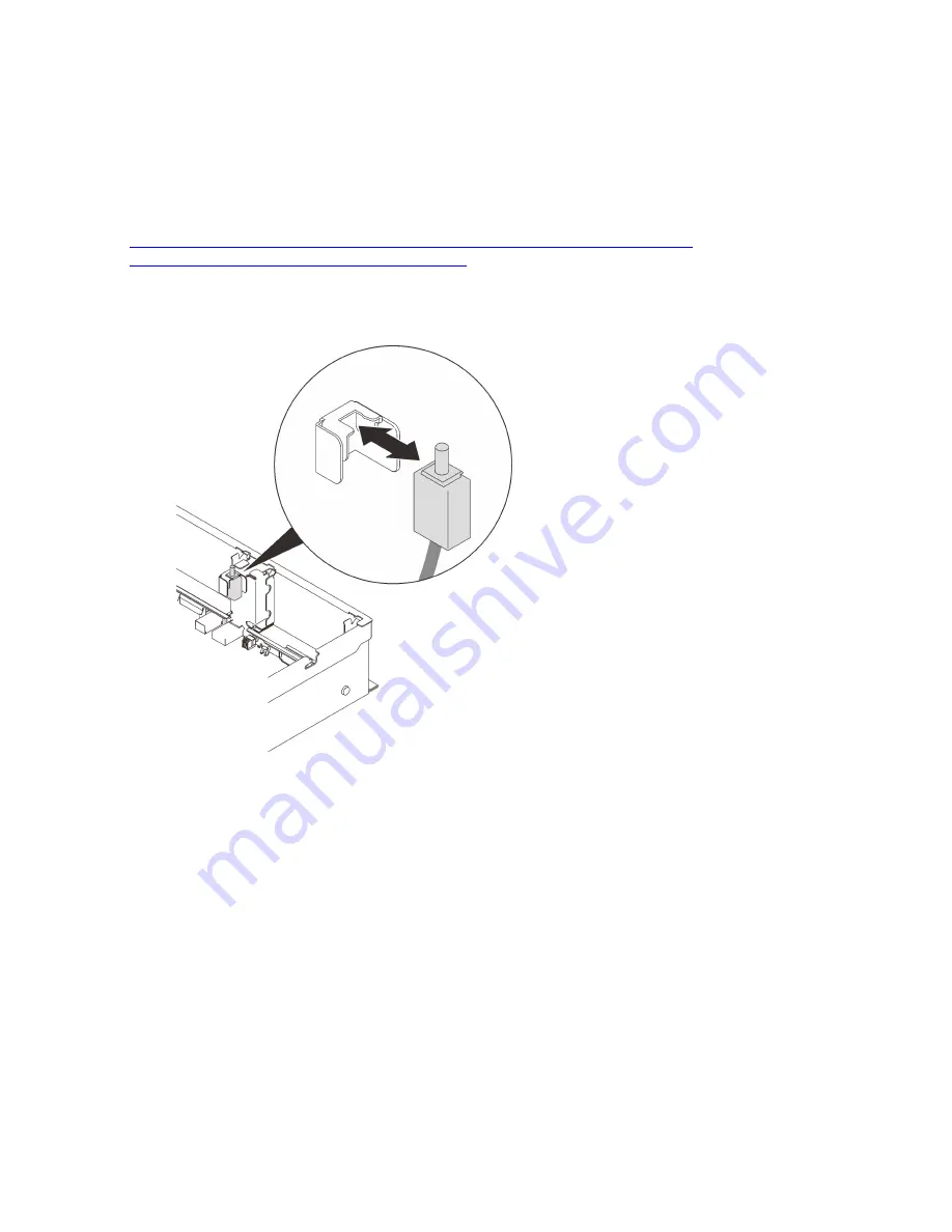
Step 1. Align the intrusion switch with the slot between the two riser zones, and push it in.
Figure 63. Installing the intrusion switch
Step 2. Connect the cable to the system board. See “System board connectors” on page 28 to locate the
connector on the system board.
After this task is completed
Proceed to complete the parts replacement (see “Complete the parts replacement” on page 218).
Memory module replacement
Follow instructions in this section to remove or install a memory module.
Memory module slot location
Locate the memory module to replace based on the following figures.
.
Hardware replacement procedures
147
Summary of Contents for 7D31
Page 1: ...ThinkSystem SR850 V2 Maintenance Manual Machine Types 7D31 and 7D32 ...
Page 8: ...vi ThinkSystem SR850 V2 Maintenance Manual ...
Page 52: ...44 ThinkSystem SR850 V2 Maintenance Manual ...
Page 60: ... Three backplanes on page 57 52 ThinkSystem SR850 V2 Maintenance Manual ...
Page 70: ...62 ThinkSystem SR850 V2 Maintenance Manual ...
Page 71: ...Chapter 3 Internal cable routing 63 ...
Page 78: ...70 ThinkSystem SR850 V2 Maintenance Manual ...
Page 114: ...106 ThinkSystem SR850 V2 Maintenance Manual ...
Page 236: ...Figure 133 System board and expansion board LEDs 228 ThinkSystem SR850 V2 Maintenance Manual ...
Page 258: ...250 ThinkSystem SR850 V2 Maintenance Manual ...
Page 260: ...252 ThinkSystem SR850 V2 Maintenance Manual ...
Page 264: ...256 ThinkSystem SR850 V2 Maintenance Manual ...
Page 273: ......
Page 274: ......


