Attention:
• Go over “Installation Guidelines” on page 107 to ensure that you work safely.
• Turn off the server and peripheral devices and disconnect the power cords and all external cables (see
“Power off the server” on page 12).
• If the server is installed in a rack, slide the server out on its rack slide rails to gain access to the top cover,
or remove the server from the rack.
• Prevent exposure to static electricity, which might lead to system halt and loss of data, by keeping static-
sensitive components in their static-protective packages until installation, and handling these devices with
an electrostatic-discharge wrist strap or other grounding system.
• Do not touch the processor contacts. Contaminants on the processor contacts, such as oil from your skin,
can cause connection failures.
• Do not allow the thermal grease on the processor or heat sink to come in contact with anything. Contact
with any surface can compromise the thermal grease, rendering it ineffective. Thermal grease can damage
components, such as the electrical connectors in the processor socket.
Note:
The heat sink, processor, and processor carrier for your system might be different than those shown
in the illustrations.
Watch the procedure
. A video of this procedure is available from the following links:
•
https://www.youtube.com/playlist?list=PLYV5R7hVcs-C6QgmsUMRG6ul0bHzrGmsG
•
https://list.youku.com/albumlist/show/id_54461099
Procedure
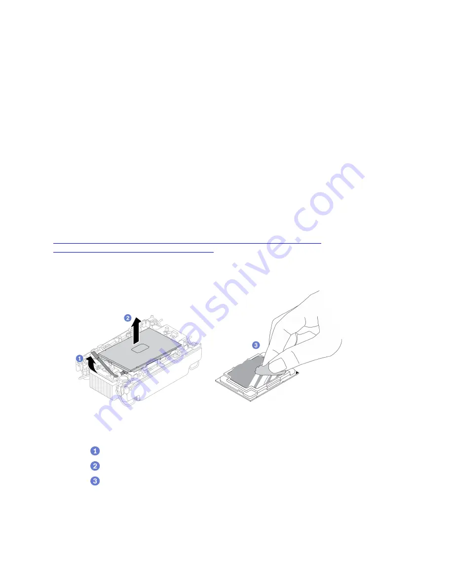
Step 1. Separate the processor from the heat sink and carrier.
Figure 97. Separating a processor from the heat sink and carrier
Note:
Do not touch the contacts on the processor.
a.
Lift the handle to release the processor from the carrier.
b.
Hold the processor by its edges; then, lift the processor from the heat sink and carrier.
c.
Without putting the processor down, wipe the thermal grease from the top of the processor
with an alcohol cleaning pad; then, place the processor on a static protective surface with the
processor-contact side up.
Step 2. Separate the processor carrier from the heat sink.
184
ThinkSystem SR850 V2 Maintenance Manual
Summary of Contents for 7D31
Page 1: ...ThinkSystem SR850 V2 Maintenance Manual Machine Types 7D31 and 7D32 ...
Page 8: ...vi ThinkSystem SR850 V2 Maintenance Manual ...
Page 52: ...44 ThinkSystem SR850 V2 Maintenance Manual ...
Page 60: ... Three backplanes on page 57 52 ThinkSystem SR850 V2 Maintenance Manual ...
Page 70: ...62 ThinkSystem SR850 V2 Maintenance Manual ...
Page 71: ...Chapter 3 Internal cable routing 63 ...
Page 78: ...70 ThinkSystem SR850 V2 Maintenance Manual ...
Page 114: ...106 ThinkSystem SR850 V2 Maintenance Manual ...
Page 236: ...Figure 133 System board and expansion board LEDs 228 ThinkSystem SR850 V2 Maintenance Manual ...
Page 258: ...250 ThinkSystem SR850 V2 Maintenance Manual ...
Page 260: ...252 ThinkSystem SR850 V2 Maintenance Manual ...
Page 264: ...256 ThinkSystem SR850 V2 Maintenance Manual ...
Page 273: ......
Page 274: ......


