Note:
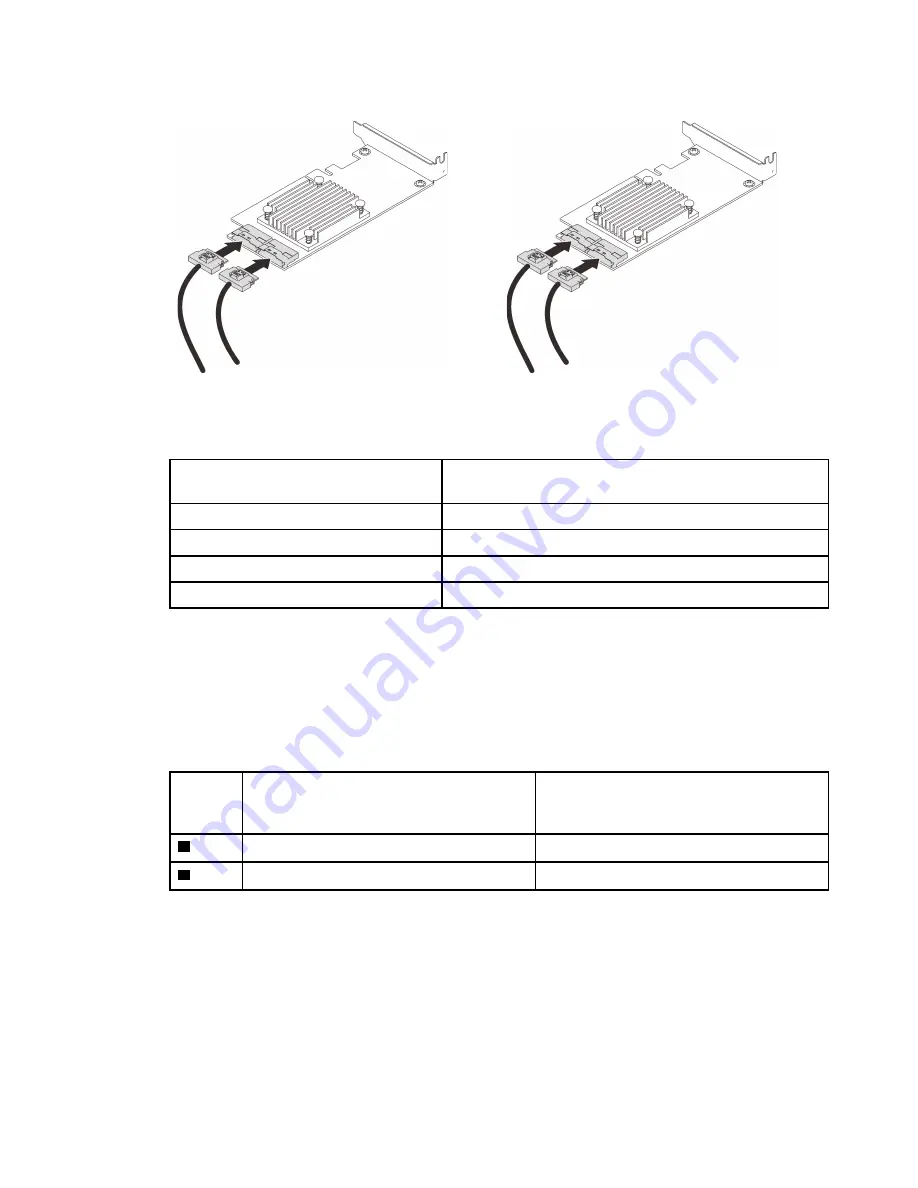
Make sure to match the drive backplane and NVMe switch card connectors as following:
Table 18. Drive backplane and NVMe switch card connectors
AnyBay/NVMe drive backplane
connector
Switch card connector
0-1
C0
2-3
C1
4-5
C0
6-7
C1
Figure 26. Connecting cables to the NVMe switch cards
Step 3. Install the two adapters into corresponding slots on the x16/x16 PCIe riser card (see “Install an
adapter in the PCIe riser assembly” on page 163).
Note:
Table 19. NVMe switch cards and corresponding PCIe slot numbers
AnyBay/NVMe drive backplane
connectors which are connected to the
NVMe switch card
PCIe slot number
1
0-1, 2-3
Slot 5
2
4-5, 6-7
Slot 6
Step 4. Install the PCIe riser card (see “Install the PCIe riser assembly” on page 165).
SAS/SATA backplane combinations
Follow the instructions in this section to learn how do cable routing for combinations with SAS/SATA
backplanes.
See the following sections for cable routing combinations with only SAS/SATA drive backplanes.
• “One backplane” on page 53
• “Two backplanes” on page 56
51
Summary of Contents for 7D31
Page 1: ...ThinkSystem SR850 V2 Maintenance Manual Machine Types 7D31 and 7D32 ...
Page 8: ...vi ThinkSystem SR850 V2 Maintenance Manual ...
Page 52: ...44 ThinkSystem SR850 V2 Maintenance Manual ...
Page 60: ... Three backplanes on page 57 52 ThinkSystem SR850 V2 Maintenance Manual ...
Page 70: ...62 ThinkSystem SR850 V2 Maintenance Manual ...
Page 71: ...Chapter 3 Internal cable routing 63 ...
Page 78: ...70 ThinkSystem SR850 V2 Maintenance Manual ...
Page 114: ...106 ThinkSystem SR850 V2 Maintenance Manual ...
Page 236: ...Figure 133 System board and expansion board LEDs 228 ThinkSystem SR850 V2 Maintenance Manual ...
Page 258: ...250 ThinkSystem SR850 V2 Maintenance Manual ...
Page 260: ...252 ThinkSystem SR850 V2 Maintenance Manual ...
Page 264: ...256 ThinkSystem SR850 V2 Maintenance Manual ...
Page 273: ......
Page 274: ......


