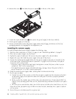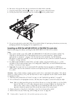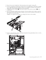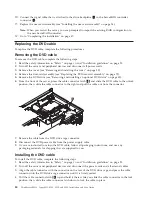
9.
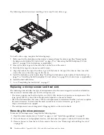
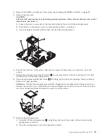
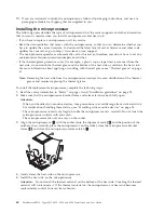
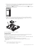
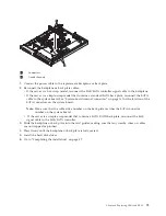
Connect the cables from the power supply to the internal devices.
10.
Install the DIMM air baffle (see “Removing and installing the DIMM air baffle” on page 31).
11.
Install the cover (see “Removing and installing the cover” on page 29).
12.
Slide the server into the rack.
13.
Reconnect the ac power cord into the connector on the back of the power supply.
14.
Reconnect all external cables that were disconnected.
15.
Connect the other end of the ac power cord into a properly grounded electrical outlet.
16.
Press the power-control button (see “Turning on the server” on page 22.
17.
Make sure that the power-on LED on the front of the server is lit.
Replacing a fan assembly
The server comes with five replaceable cooling fans. Use the following procedures to replace a fan.
Removing a fan assembly
To remove any of the five replaceable fans, complete the following steps:
1.
Read the safety information in “Safety” on page vii and “Installation guidelines” on page 25.
2.
Turn off the server and all peripheral devices, and disconnect the power cords and all external cables.
3.
Remove the server from the rack and remove the cover (see “Removing and installing the cover” on
page 29).
4.
Reconnect the power cord; then, turn on the server.
Attention:
Operating the server for extended periods of time (more than 30 minutes) with the cover
removed might damage server components.
5.
Determine which fan to replace by checking the LEDs on the system board (see “System-board LEDs”
on page 21); a lit LED indicates the fan to replace.
6.
Turn off the server; then, disconnect the power cord again.
7.
Remove the DIMM air baffle (see “Removing and installing the DIMM air baffle” on page 31).
8.
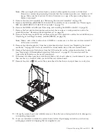
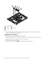
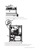
Remove the failed fan from the server:
a.
Disconnect the fan cable from the system board (see “System-board internal connectors” on page
16). You may need to disengage the cables from cable retention clips. Note the routing of the fan
cable to the connector; you will have to route the fan cable the same way when you install the fan.
b.
Grasp the top of the fan with your index finger and thumb and lift the fan out of the server.
Chapter 6. Replacing CRUs and FRUs
67
Summary of Contents for 653417U
Page 1: ...Installation and User Guide ThinkServer RS210 Machine Types 6531 6532 6533 and 6534 ...
Page 2: ......
Page 3: ...ThinkServer RS210 Types 6531 6532 6533 and 6534 Installation and User Guide ...
Page 8: ...vi ThinkServer RS210 Types 6531 6532 6533 and 6534 Installation and User Guide ...
Page 16: ...xiv ThinkServer RS210 Types 6531 6532 6533 and 6534 Installation and User Guide ...
Page 20: ...4 ThinkServer RS210 Types 6531 6532 6533 and 6534 Installation and User Guide ...
Page 22: ...6 ThinkServer RS210 Types 6531 6532 6533 and 6534 Installation and User Guide ...
Page 40: ...24 ThinkServer RS210 Types 6531 6532 6533 and 6534 Installation and User Guide ...
Page 66: ...50 ThinkServer RS210 Types 6531 6532 6533 and 6534 Installation and User Guide ...
Page 128: ...112 ThinkServer RS210 Types 6531 6532 6533 and 6534 Installation and User Guide ...
Page 160: ...144 ThinkServer RS210 Types 6531 6532 6533 and 6534 Installation and User Guide ...
Page 164: ...148 ThinkServer RS210 Types 6531 6532 6533 and 6534 Installation and User Guide ...
Page 173: ...Chinese Class A warning statement Korean Class A warning statement Appendix B Notices 157 ...
Page 174: ...158 ThinkServer RS210 Types 6531 6532 6533 and 6534 Installation and User Guide ...
Page 179: ......
Page 180: ...Printed in USA ...

