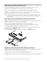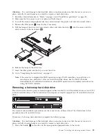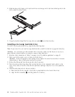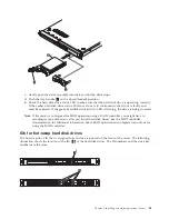
Removing and installing the cover
Important:
Before you install optional hardware, make sure that the server is working correctly. Start the
server, and make sure that the operating system starts, if an operating system is installed, or that an
I9990305 error code is displayed, indicating that an operating system was not found but the server is
otherwise working correctly. If the server is not working correctly, see the
Hardware Maintenance Manual
for troubleshooting information.
Removing the cover
To remove the server cover, do the following:
1.
Read the safety information in “Safety” on page vii and “Installation guidelines” on page 25.
2.
Turn off the server and peripheral devices and disconnect the power cords and all external cables, if
necessary.
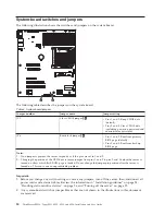
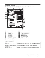
Note:
When you disconnect the power source from the server, you will lose the ability to view the
LEDs because the LEDs will not be lit with the power source removed. Before disconnecting
the power source, make sure to note which LEDs are lit, including the LEDs that are lit on the
operator information panel and LEDs that are lit inside the server on the system board; then,
see the
Hardware Maintenance Manual
for information on how to solve the problem.
3.
If the server has been installed in a rack, slide the server out from the rack enclosure. See the
Rack
Installation Instructions
that come with the server for information about removing the server from the
rack.
4.
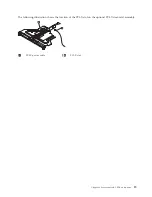
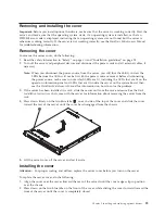
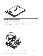
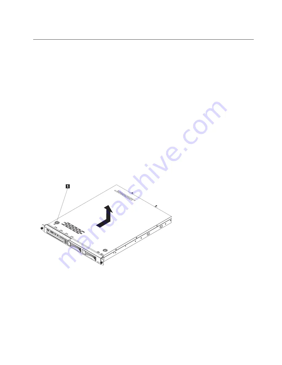
Press down firmly on the two blue tabs
1
on each side of the top of the cover and slide the cover
toward the rear of the server until the cover has disengaged from the chassis.
5.
Lift the server cover off the server and set it aside.
Installing the cover
Attention:
For proper cooling and airflow, replace the server cover before you turn on the server.
To replace the server cover, do the following:
1.
Align the cover over the server (toward the rear of the server) until the cover edges slip in position
over the chassis.
2.
Press down on the two blue tabs on the front of the cover, while sliding the cover forward toward the
front of the server until the cover is completely closed.
Chapter 5. Installing and replacing optional devices
29
Summary of Contents for 653417U
Page 1: ...Installation and User Guide ThinkServer RS210 Machine Types 6531 6532 6533 and 6534 ...
Page 2: ......
Page 3: ...ThinkServer RS210 Types 6531 6532 6533 and 6534 Installation and User Guide ...
Page 8: ...vi ThinkServer RS210 Types 6531 6532 6533 and 6534 Installation and User Guide ...
Page 16: ...xiv ThinkServer RS210 Types 6531 6532 6533 and 6534 Installation and User Guide ...
Page 20: ...4 ThinkServer RS210 Types 6531 6532 6533 and 6534 Installation and User Guide ...
Page 22: ...6 ThinkServer RS210 Types 6531 6532 6533 and 6534 Installation and User Guide ...
Page 40: ...24 ThinkServer RS210 Types 6531 6532 6533 and 6534 Installation and User Guide ...
Page 66: ...50 ThinkServer RS210 Types 6531 6532 6533 and 6534 Installation and User Guide ...
Page 128: ...112 ThinkServer RS210 Types 6531 6532 6533 and 6534 Installation and User Guide ...
Page 160: ...144 ThinkServer RS210 Types 6531 6532 6533 and 6534 Installation and User Guide ...
Page 164: ...148 ThinkServer RS210 Types 6531 6532 6533 and 6534 Installation and User Guide ...
Page 173: ...Chinese Class A warning statement Korean Class A warning statement Appendix B Notices 157 ...
Page 174: ...158 ThinkServer RS210 Types 6531 6532 6533 and 6534 Installation and User Guide ...
Page 179: ......
Page 180: ...Printed in USA ...

