background image

Enabling the remote presence feature

To enable the remote presence feature, complete the following steps:

1.

Install the virtual media key into the dedicated slot on the system board (see “Installing the virtual
media key” on page 82).

2.

Turn on the server.

Note:

Approximately 1 to 3 minutes after the server is connected to ac power, the power-control
button becomes active.

Obtaining the IP address for the IMM

To access the Web interface, you need the IP address for the IMM. You can obtain the IMM IP address
through the Setup utility. The server comes with a default IP address for the IMM of 192.168.70.125. To
locate the IP address, complete the following steps:

1.

Turn on the server.

Note:

Approximately 1 to 3 minutes after the server is connected to ac power, the power-control
button becomes active.

2.

When the prompt

<F1> Setup

is displayed, press F1. (This prompt is displayed on the screen for only

a few seconds. You must press F1 quickly.) If you have set both a power-on password and an
administrator password, you must type the administrator password to access the full Setup utility
menu.

3.

From the Setup utility main menu, select

System Settings

.

4.

On the next screen, select

Integrated Management Module

.

5.

On the next screen, select

Network Configuration

.

6.

Find the IP address and write it down.

7.

Exit from the Setup utility.

Logging on to the Web interface

To log on to the Web interface to use the remote presence functions, complete the following steps:

1.

Open a Web browser and in the

address

or

URL

field, type the IP address or host name of the IMM

to which you want to connect.

Note:

The IMM defaults to DHCP. If a DHCP host is not available, the IMM assigns a static IP
address of 192.168.70.125.

2.

On the Login page, type the user name and password. If you are using the IMM for the first time,
you can obtain the user name and password from your system administrator. All login attempts are
documented in the event log.

Note:

The IMM is set initially with a user name of USERID and password of PASSW0RD (passw0rd
with a zero, not a the letter O). You have read/write access. You must change the default
password the first time you log on.

3.

On the Welcome page, type a timeout value (in minutes) in the field that is provided. The IMM will
log you off of the Web interface if your browser is inactive for the number of minutes that you
entered for the timeout value.

4.

Click

Continue

to start the session. The System Health page provides a quick view of the system

status.

Chapter 7. Configuring the server

109

Summary of Contents for 653417U

Page 1: ...Installation and User Guide ThinkServer RS210 Machine Types 6531 6532 6533 and 6534 ...

Page 2: ......

Page 3: ...ThinkServer RS210 Types 6531 6532 6533 and 6534 Installation and User Guide ...

Page 4: ...ation 2007 2009 LENOVO products data computer software and services have been developed exclusively at private expense and are sold to governmental entities as commercial items as defined by 48 C F R 2 101 with limited and restricted rights to use reproduction and disclosure LIMITED AND RESTRICTED RIGHTS NOTICE If products data computer software or services are delivered pursuant a General Service...

Page 5: ... IDs for hot swap hard disk drives 41 Installing an optional PCI card 42 Removing and installing an optional DVD drive 45 Removing a DVD drive 45 Installing a DVD drive 46 Completing the installation 47 Connecting the cables 48 Updating the server configuration 49 Chapter 6 Replacing CRUs and FRUs 51 Replacing a PCI card 51 Removing a PCI card 51 Installing a PCI card 52 Replacing a USB embedded h...

Page 6: ...the IP address for the IMM 109 Logging on to the Web interface 109 Enabling the Intel Gigabit Ethernet Utility program 110 Configuring the Gigabit Ethernet controllers 110 Enabling and configuring Serial over LAN SOL 110 UEFI update and configuration 110 Chapter 8 Solving problems 113 Diagnostic tools 113 POST 113 Error logs 114 POST error codes 115 Troubleshooting tables 122 EasyStartup problems ...

Page 7: ...ce statement 154 German Class A compliance statement 154 Japanese Voluntary Control Council for Interference VCCI statement 155 Japanese recycling statements 155 Taiwanese Class A warning statement 156 Chinese Class A warning statement 157 Korean Class A warning statement 157 Index 159 Contents v ...

Page 8: ...vi ThinkServer RS210 Types 6531 6532 6533 and 6534 Installation and User Guide ...

Page 9: ...rst de veiligheidsvoorschriften Ennen kuin asennat tämän tuotteen lue turvaohjeet kohdasta Safety Information Avant d installer ce produit lisez les consignes de sécurité Vor der Installation dieses Produkts die Sicherheitshinweise lesen Prima di installare questo prodotto leggere le Informazioni sulla Sicurezza Les sikkerhetsinformasjonen Safety Information før du installerer dette produktet Ante...

Page 10: ...ons of the caution or danger statement in the Safety Information document For example if a caution statement is labeled Statement 1 translations for that caution statement are in the Safety Information document under Statement 1 Be sure to read all caution and danger statements in this document before you perform the procedures Read any additional safety information that comes with the server or o...

Page 11: ...equipment when there is evidence of fire water or structural damage v Disconnect the attached power cords telecommunications systems networks and modems before you open the device covers unless instructed otherwise in the installation and configuration procedures v Connect and disconnect cables as described in the following table when installing moving or opening covers on this product or attached...

Page 12: ...y replace it only with the same module type made by the same manufacturer The battery contains lithium and can explode if not properly used handled or disposed of Do not v Throw or immerse into water v Heat to more than 100 C 212 F v Repair or disassemble Dispose of the battery as required by local ordinances or regulations x ThinkServer RS210 Types 6531 6532 6533 and 6534 Installation and User Gu...

Page 13: ...the device v Use of controls or adjustments or performance of procedures other than those specified herein might result in hazardous radiation exposure DANGER Some laser products contain an embedded Class 3A or Class 3B laser diode Note the following Laser radiation when open Do not stare into the beam do not view directly with optical instruments and avoid direct exposure to the beam Class 1 Lase...

Page 14: ... and the power switch on the power supply do not turn off the electrical current supplied to the device The device also might have more than one power cord To remove all electrical current from the device ensure that all power cords are disconnected from the power source 1 2 xii ThinkServer RS210 Types 6531 6532 6533 and 6534 Installation and User Guide ...

Page 15: ...as this label attached There are no serviceable parts inside these components If you suspect a problem with one of these parts contact a service technician Statement 26 CAUTION Do not place any object on top of rack mounted devices This server is suitable for use on an IT power distribution system whose maximum phase to phase voltage is 240 V under any distribution fault condition Safety xiii ...

Page 16: ...xiv ThinkServer RS210 Types 6531 6532 6533 and 6534 Installation and User Guide ...

Page 17: ...server The server comes with the ThinkServer EasyStartup DVD to help you configure the hardware install device drivers and install the operating system This server supports one of the following hard disk drive configurations v Up to four 2 5 inch hot swap Serial Attached SCSI SAS hard disk drives v Up to two 3 5 inch hot swap SAS hard disk drives v Up to two 3 5 inch simple swap SAS hard disk driv...

Page 18: ...s placed just before the instruction or situation in which damage might occur v Caution These statements indicate situations that can be potentially hazardous to you A caution statement is placed just before the description of a potentially hazardous procedure step or situation v Danger These statements indicate situations that can be potentially lethal or extremely hazardous to you A danger state...

Page 19: ...ted and provided in server packaging Additional languages are provided on the ThinkServer Documentation DVD and on the Lenovo Support Web site Hardware Maintenance Manual This document provides diagnostic information parts listing and replacement procedures for all field replaceable units parts replaced by trained service personnel as well as all customer replaceable units CRUs Lenovo Support Web ...

Page 20: ...4 ThinkServer RS210 Types 6531 6532 6533 and 6534 Installation and User Guide ...

Page 21: ...AID controllers and arrays Configuring RAID controllers on page 95 Install operating system and basic drivers Using the EasyStartup DVD on page 100 Install any additional drivers needed for added features Refer to the instructions that came with the hardware option Configure Ethernet settings in operating system See the operating system help This step is not required if the operating system was in...

Page 22: ...6 ThinkServer RS210 Types 6531 6532 6533 and 6534 Installation and User Guide ...

Page 23: ...e server supports one Intel Xeon dual core or quad core microprocessor v Integrated management module The Integrated management module IMM combines service processor functions video controller and when an optional virtual media key is installed remote presence function in a single chip The IMM provides advanced service processor control monitoring and alerting function If an environmental conditio...

Page 24: ... Gigabit Ethernet controller which supports connection to a 10 Mbps 100 Mbps or 1000 Mbps network For more information see Configuring the Gigabit Ethernet controllers on page 110 v Integrated Trust Platform Module This integrated security chip performs cryptographic functions and stores private and public secure keys It provides the hardware support for the Trusted Computing Group TCG specificati...

Page 25: ...ontrollers and service processors The diagnostics programs create a merged log that includes events from all collected logs The information is collected into a file that you can send to the Lenovo technical support team to help diagnose a problem Additionally you can view the information locally through a generated text report file You also can copy the log to a removable medium and view the HTML ...

Page 26: ... expansion bays depending on the model One of the following configurations v Four 2 5 inch hot swap SAS hard disk drive bays v Two 3 5 inch hot swap SAS or hot swap SATA hard disk drive bays v Two 3 5 inch simple swap SAS hard disk drive bays PCI expansion slots Supports two PCI riser slots on the riser card that connects to slots 1 and 2 on the system board v Slot 1 supports low profile cards PCI...

Page 27: ...tage low range Minimum 100 V ac Maximum 127 V ac v Input voltage high range Minimum 200 V ac Maximum 240 V ac v Input kilovolt amperes kVA approximately Minimum 0 102 kVA Maximum 0 55 kVA Notes 1 Power consumption and heat output vary depending on the number and type of optional features installed and the power management optional features in use 2 The sound levels were measured in controlled acou...

Page 28: ...ontrollers v ECC memory v Error codes and messages v Hot swap hard disk drives v Integrated management module IMM v Menu driven setup system configuration and redundant array of independent disks RAID configuration programs v Parity checking on the small computer system interface SCSI bus and PCI buses v Power management Compliance with Advanced Configuration and Power Interface ACPI v Power on se...

Page 29: ...een on 3 5 inch hot swap SAS server model Hard disk drive status LED amber on 2 5 inch hot swap SAS server model 5 Locator LED 10 Hard disk drive status LED amber on 3 5 inch hot swap SAS server model Hard disk drive activity LED green on 2 5 inch hot swap SAS server model Following is an explanation of the controls light emitting diodes LEDs and connectors on the front of the ThinkServer RS210 v ...

Page 30: ...y of these connectors v DVD eject button Press this button to release a DVD or CD from the DVD drive v DVD drive activity LED When this LED is lit it indicates that the DVD drive is in use v Hot swap hard disk drive activity LEDs some models Each hot swap hard disk drive has an activity LED and when this LED is flashing it indicates that the drive is in use This LED is used on SAS or SATA hard dis...

Page 31: ...her of these connectors to connect the server to a network When you use the Ethernet 1 connector the network can be shared with the IMM through a single network cable v NMI button Press this button to force a nonmaskable interrupt to the microprocessor You might have to use a pen or the end of a straightened paper clip to press the button It allows you to blue screen the server and take a memory d...

Page 32: ...r 23 Battery 4 DIMM 4 14 Simple swap HDD backplane signal connector 24 Power 2 connector 5 DIMM 5 15 Wake on LAN connector 25 Virtual media key connector 6 DIMM 6 16 Optical drive DVD connector 26 Power 1 connector 7 Microprocessor 17 Hypervisor flash device connector 27 Power 3 connector 8 Fan 3 connector 18 Reserved 28 Power 4 connector 9 Fan 2 connector 19 Reserved 29 Fan 5 connector 10 ServeRA...

Page 33: ... connectors on the system board Microprocessor Heatsink Orientation DIMMs DIMMs 1 Serial com 1 connector 5 Ethernet connector 2 2 Video connector 6 USB connectors 3 and 4 3 Ethernet connector 1 7 SW1 NMI button 4 USB connectors 1 and 2 Chapter 4 Server controls LEDs and power 17 ...

Page 34: ...9 Hypervisor flash device connector 3 DIMM 3 10 Riser card connector 2 4 DIMM 4 11 Riser card connector 1 5 DIMM 5 12 Battery 6 DIMM 6 13 Virtual media key connector 7 ServeRAID BR10il v2 SAS SATA controller connector The following illustration shows the locations of the PCI Express slots on the riser card assembly 1 PCI Express x8 slot 1 2 PCI Express x8 slot 2 18 ThinkServer RS210 Types 6531 653...

Page 35: ...The following illustration shows the location of the PCI X slot on the optional PCI X riser card assembly 1 PCI X power cable 2 PCI X slot Chapter 4 Server controls LEDs and power 19 ...

Page 36: ...server responds as if the pins are set to 1 and 2 2 Changing the position of the UEFI boot recovery jumper from pins 1 and 2 to pins 2 and 3 before the server is turned on alters which flash ROM page is loaded Do not change the jumper pin position after the server is turned on This can cause an unpredictable problem Important 1 Before you change any switch settings or move any jumpers turn off the...

Page 37: ...error LED 13 Standby power LED 6 Fan 1 error LED 14 System board error LED 7 SAS SATA Controller LED 15 DIMM 1 6 error LEDs 8 IMM heart beat LED Table 5 System board LEDs LED Description Error LEDs When one of these LEDs is lit it indicates that the associated component has failed Baseboard management controller heartbeat LED This LED flashes to indicate that the IMM is functioning normally Standb...

Page 38: ...urned on in any of the following ways v If a power failure occurs while the server is turned on the server will restart automatically when power is restored v If your operating system supports the Wake on LAN feature the Wake on LAN feature can turn on the server Note When 4 GB or more of memory physical or logical is installed some memory is reserved for various system resources and is unavailabl...

Page 39: ...r operating system supports this feature After an orderly shutdown of the operating system the server will turn off automatically v You can press the power control button to start an orderly shutdown of the operating system and turn off the server if your operating system supports this feature v If the operating system stops functioning you can press and hold the power control button for more than...

Page 40: ...24 ThinkServer RS210 Types 6531 6532 6533 and 6534 Installation and User Guide ...

Page 41: ...d but the server is otherwise working correctly If the server is not working correctly see the Hardware Maintenance Manual for diagnostic information v Observe good housekeeping in the area where you are working Place removed covers and other parts in a safe place v If you must start the server while the cover is removed make sure that no one is near the server and that no tools or other objects h...

Page 42: ... is powered on might cause the server to halt which might result in the loss of data To avoid this potential problem always use an electrostatic discharge wrist strap or other grounding system when you work inside the server with the power on You might be instructed to turn on the server while the cover is off to look at system board LEDs Follow these guidelines when you work inside a server that ...

Page 43: ... its package and install it directly into the server without setting down the device If it is necessary to set down the device put it back into its static protective package Do not place the device on the server cover or on a metal surface v Take additional care when you handle devices during cold weather Heating reduces indoor humidity and increases static electricity Chapter 5 Installing and rep...

Page 44: ...or information panel 4 Power supply 15 Fans 5 SAS SATA backplane some models 16 System board 6 SATA simple swap back panel some models 17 Microprocessor 7 3 5 inch drive cage 18 Heat sink 8 3 5 inch simple swap SATA hard disk drive some models 19 Cover 9 Simple swap SATA filler 10 Hot swap hard disk drive filler 11 3 5 inch or 2 5 inch hot swap hard disk drive depending on model 28 ThinkServer RS2...

Page 45: ...h LEDs are lit including the LEDs that are lit on the operator information panel and LEDs that are lit inside the server on the system board then see the Hardware Maintenance Manual for information on how to solve the problem 3 If the server has been installed in a rack slide the server out from the rack enclosure See the Rack Installation Instructions that come with the server for information abo...

Page 46: ...e 29 2 From inside the server press the bezel release latch 1 toward the left side of the server 3 Pivot the bezel 2 forward and pull it away from the server 4 If you are instructed to return the bezel follow all packaging instructions and use any packaging materials for shipping that are supplied to you 30 ThinkServer RS210 Types 6531 6532 6533 and 6534 Installation and User Guide ...

Page 47: ...25 2 Turn off the server and peripheral devices and disconnect all power cords and external cables 3 Remove the server from the rack and remove the cover see Removing and installing the cover on page 29 4 Lift the DIMM air baffle 1 up and out of the server Attention For proper cooling and airflow reinstall the DIMM air baffle before you turn on the server Operating the server with the air baffle r...

Page 48: ...organization wwwww is the DIMM bandwidth in MBps 6400 6 40 GBps PC3 800 SDRAMs 8 byte primary data bus 8500 8 53 GBps PC3 1066 SDRAMs 8 byte primary data bus 10600 10 66 GBps PC3 1333 SDRAMs 8 byte primary data bus 12800 12 80 GBps PC3 1600 SDRAMs 8 byte primary data bus m is the DIMM type E Unbuffered DIMM UDIMM with ECC x72 bit module data bus R Registered DIMM RDIMM U Unbuffered DIMM with no EC...

Page 49: ...ing ranked UDIMMs Table 7 Maximum memory population using ranked UDIMMs depending on your model Number of UDIMMs DIMM type Size Total memory 4 Single rank UDIMMs 1 GB 4 GB 4 Single rank UDIMMs 2 GB 8 GB 4 Dual rank UDIMMs 2 GB 8 GB 4 Dual rank UDIMMs 4 GB when available 16 GB v The following table shows the UDIMM memory population rule to optimize the system performance Table 8 UDIMM population ru...

Page 50: ...B 16 GB 4 Quad rank RDIMMs 4 GB 16 GB 6 Dual rank RDIMMs 4 GB 24 GB 4 Quad rank RDIMMs 8 GB when available 32 GB v The following table shows the RDIMM memory population rule to optimize the system performance Table 11 RDIMM population rule for dual channel symmetric mode DIMM connector 1 DIMM connector 2 DIMM connector 3 DIMM connector 4 DIMM connector 5 DIMM connector 6 Populated Empty Empty Empt...

Page 51: ...e following steps 1 Read the safety information in Safety on page vii and Installation guidelines on page 25 2 Turn off the server and peripheral devices and disconnect the power cords and all external cables if necessary 3 Remove the cover see Removing and installing the cover on page 29 Attention To ensure proper cooling and airflow do not operate the server for more than 30 minutes with the cov...

Page 52: ...the same pair v When you install or remove DIMMs the server configuration information changes When you restart the server the system displays a message that indicates that the memory configuration has changed See System board internal connectors on page 16 for the location of the DIMM connectors on the system board To install a DIMM complete the following steps 1 Read the safety information in Saf...

Page 53: ...IMM from the package 8 Turn the DIMM 1 so that the DIMM keys align correctly with the connector see System board internal connectors on page 16 for the locations of the DIMM connectors 9 Insert the DIMM into the connector by aligning the edges of the DIMM with the slots at the ends of the DIMM connector 10 Firmly press the DIMM straight down into the connector by applying pressure on both ends of ...

Page 54: ...all power from the server before you remove or install a simple swap hard disk drive To remove a simple swap SATA drive from the bay complete the following steps 1 Read the safety information in Safety on page vii and Installation guidelines on page 25 2 Make sure that the server cover is in place and fully closed 3 Turn off the server and peripheral devices and disconnect the power cord and all e...

Page 55: ... using a RAID controller you might have to reconfigure your disk arrays after you install hard disk drives See the RAID controller documentation for additional information about RAID operation and complete instructions for using the RAID controller Removing a hot swap hard disk drive The 3 5 inch drive hot swap server models support either two SAS 3 5 inch hard disk drives or two SATA 3 5 inch har...

Page 56: ... Safety on page vii and Installation guidelines on page 25 2 Make sure that the server cover is in place and fully closed Attention To maintain proper system cooling do not operate the server for more than 10 minutes without either a drive or filler panel installed in each bay 3 Remove the filler panel from the empty drive bay if necessary 4 Touch the static protective package that contains the dr...

Page 57: ...d Note If the server is configured for RAID operation using a RAID controller you might have to reconfigure your disk arrays after you install hard disk drives See the RAID controller documentation for additional information about RAID operation and complete instructions for using the RAID controller IDs for hot swap hard disk drives The hot swap drive ID that is assigned to each drive is printed ...

Page 58: ...rter length PCI X 64 133 MHz PCI card in the PCI X slot on the riser card assembly The server does not support full length PCI cards v The server uses a rotational interrupt technique to configure PCI Express PCI cards so that you can install PCI Express PCI cards that do not support sharing of interrupts To ensure that your ServeRAID controllers function properly on UEFI based servers make sure t...

Page 59: ...r and peripheral devices and disconnect the power cords and all external cables then remove the server cover see Removing and installing the cover on page 29 3 If you have installed an optional PCI X riser card assembly 2 disconnect the riser card power cable 1 from the riser card assembly 4 Grasp the riser card at the front grip point and rear edges then lift to remove the riser card assembly Pla...

Page 60: ...nector on the PCI card with the connector on the riser card assembly Press the edge of the connector firmly into the riser card assembly Make sure that the PCI card snaps into the riser card assembly securely Important Make sure that the U shaped opening in the metal PCI card bracket 4 engages the tab 2 on the expansion slot bracket 1 Attention When you install an PCI card make sure that the PCI c...

Page 61: ...afety information in Safety on page vii and Installation guidelines on page 25 2 Turn off the server and peripheral devices and disconnect all power cords 3 Remove the cover see Removing and installing the cover on page 29 4 Pull the release tab 1 the rear of the drive retention clip toward the right side of the server to release the clip then while you pull the tab push the drive out of the bay N...

Page 62: ...D drive complete the following steps 1 Read the safety information in Safety on page vii and Installation guidelines on page 25 2 Turn off the server and peripheral devices and disconnect the power cords and all external cables 3 Remove the cover see Removing and installing the cover on page 29 4 Touch the static protective package that contains the new DVD drive to any unpainted metal surface on ...

Page 63: ...Klasse 1 Laser Klass 1 Luokan 1 Laserlaite Appareil A Laser de Classe 1 7 Slide the drive into the DVD drive bay until the drive clicks into place 8 Go to Completing the installation Completing the installation To complete the installation do the following 1 If the DIMM air baffle is not in place reinstall it now see Removing and installing the DIMM air baffle on page 31 2 Reinstall the cover if i...

Page 64: ...of the server 1 Power on LED 6 System error LED 2 Power control button 7 USB 1 connector 3 Reset button 8 USB 2 connector 4 Hard disk drive activity LED 9 Hard disk drive activity LED green 5 Locator LED 10 Hard disk drive status LED amber 48 ThinkServer RS210 Types 6531 6532 6533 and 6534 Installation and User Guide ...

Page 65: ...ptional devices Use these identifiers to connect the cables to the correct connectors Updating the server configuration When you start the server for the first time after you add or remove an internal option or external device you might receive a message that the configuration has changed The UEFI Setup Utility program starts automatically so that you can save the new configuration settings Some o...

Page 66: ...50 ThinkServer RS210 Types 6531 6532 6533 and 6534 Installation and User Guide ...

Page 67: ... vii and Installation guidelines on page 25 2 Turn off the server and peripheral devices and disconnect all power cords 3 Remove the server from the rack and remove the cover see Removing and installing the cover on page 29 4 Disconnect any cables from the PCI card 5 Remove the riser card assembly see Removing the riser card assembly on page 75 6 If the riser card assembly is an optional PCI X ris...

Page 68: ...the following procedures Removing a USB embedded hypervisor flash device To remove a hypervisor flash device complete the following steps 1 Read the safety information in Safety on page vii and Installation guidelines on page 25 2 Turn off the server and peripheral devices and disconnect the power cords 3 Remove the cover see Removing and installing the cover on page 29 4 Remove the riser card ass...

Page 69: ...d assembly on page 75 5 Unlock the retention latch on the USB connector by squeezing the two retention clips toward each other see System board internal connectors on page 16 6 Align the flash device with the USB connector on the system board and push it into the USB connector until it is firmly seated 7 Press down on the retention latch to lock the flash device into the USB connector 8 Install th...

Page 70: ...all packaging instructions and use any packaging materials for shipping that are supplied to you Installing the operator information panel assembly To install the replacement operator information panel assembly complete the following steps 1 Guide the operator information panel assembly into position on top of the DVD bay housing Make sure that the LEDs and the USB connectors are aligned with the ...

Page 71: ...ion panel connector 4 Go to Completing the installation on page 47 Replace the drive cage To replace the drive cage use the following procedures Removing the drive cage The following illustration shows removing a simple swap 3 5 inch drive cage The following illustration shows removing a hot swap 3 5 inch drive cage Chapter 6 Replacing CRUs and FRUs 55 ...

Page 72: ...e cage see Removing and installing hard disk drives on page 38 4 Remove the cover see Removing and installing the cover on page 29 Attention To ensure proper cooling and airflow do not operate the server for more than 30 minutes with the cover removed 5 Remove the hard disk drive backplane or back plate v 2 5 inch drive models Remove the hard disk drive backplane from the cage See Replacing the SA...

Page 73: ...place 7 Slide the drive cage forward and remove it from the server 8 If you are instructed to return the drive cage follow all packaging instructions and use any packaging materials for shipping that are supplied to you Installing a drive cage The following illustration shows installing a simple swap 3 5 inch drive cage The following illustration shows installing a hot swap 3 5 inch drive cage Cha...

Page 74: ...cing a microprocessor and heat sink The following notes describe the type of microprocessor that the server supports and other information that you must consider when you install a microprocessor v The server supports one Intel land grid array LGA 1156 dual core or quad core microprocessor The type speed and L3 cache of the microprocessor depends on the server model v Read the documentation that c...

Page 75: ... flat surface 7 Release the microprocessor retention latch 2 by pressing down on the end moving it to the side and releasing it to the open up position 8 Open the microprocessor bracket frame 3 by lifting up the tab on the top edge Keep the bracket frame in the open position Attention Handle the microprocessor carefully Dropping the microprocessor during removal can damage the contacts Also contam...

Page 76: ...roys the even distribution of the thermal grease and requires replacing the thermal grease To install the replacement microprocessor complete the following steps 1 Read the safety information in Safety on page vii and Installation guidelines on page 25 2 Make sure that the microprocessor bracket frame and release latch are both fully open Attention v When you handle static sensitive devices take p...

Page 77: ...ntil the screws are tight Do not overtighten the screws by using excessive force 6 Go to Completing the installation on page 47 Thermal grease The thermal grease must be replaced whenever the heat sink has been removed from the top of the microprocessor and is going to be reused or when debris is found in the grease When you are installing the heat sink on the same microprocessor that is was remov...

Page 78: ... the syringe If the grease is properly applied approximately half 0 22 mL of the grease will remain in the syringe 6 Install the heat sink onto the microprocessor as described in Installing the microprocessor on page 60 Replacing the system board To replace the system board use the following procedures Removing the system board Note When you replace the system board you must either update the serv...

Page 79: ...2 Note Make a note of the location of each DIMM as you remove it so that you can later reinstall it in the same connector 9 Remove the virtual media key from the system board and set it aside see Replacing the virtual media key on page 82 You must reinstall the virtual media key on the new system board 10 Remove the hypervisor flash device from the USB connector on the system board and set it asid...

Page 80: ...page 36 5 Reinstall the DIMM air baffle see Removing and installing the DIMM air baffle on page 31 6 If necessary reinstall ServeRAID BR10il v2 SAS SATA controller see Installing an IBM ServeRAID BR10il v2 SAS SATA controller on page 78 7 Reinstall the PCI riser card assemblies and PCI cards if any were installed see Installing the riser card assembly on page 76 and Installing an optional PCI card...

Page 81: ...ply complete the following steps 1 Read the safety information in Safety on page vii and Installation guidelines on page 25 2 Disconnect the ac power cord from the connector on the power supply Disconnect all external cables from the server 3 Remove the server from the rack and remove the cover see Removing and installing the cover on page 29 Attention To ensure proper cooling and airflow do not o...

Page 82: ...nnectors on the system board v For power supply without advanced energy management connect the power cables to power connectors 1 and 2 on the system board v For high efficient power supply with advanced energy manage connect the power cables to power connectors 1 2 3 and 4 on the system board 6 Route the internal power supply cables securing them with the retention clips 7 Test the power supply a...

Page 83: ...urn off the server and all peripheral devices and disconnect the power cords and all external cables 3 Remove the server from the rack and remove the cover see Removing and installing the cover on page 29 4 Reconnect the power cord then turn on the server Attention Operating the server for extended periods of time more than 30 minutes with the cover removed might damage server components 5 Determi...

Page 84: ...mbly To install the replacement fan complete the following steps 1 Position the replacement fan so that the airflow arrow on the fan points toward the rear of the server Note Correct airflow is from the front to the rear of the server 2 Install the replacement fan in the bracket a Make sure that the fan cable 1 sits in the channel on the side of the fan 68 ThinkServer RS210 Types 6531 6532 6533 an...

Page 85: ... board battery To replace the system board battery complete the following procedures Removing the battery To remove the battery complete the following steps 1 Read the safety information in Safety on page vii and Installation guidelines on page 25 2 Turn off the server and peripheral devices and disconnect the power cords and all external cables 3 Remove the cover see Removing and installing the c...

Page 86: ...ormation Installing the battery The following notes describe information that you must consider when replacing the system board battery in the server v When replacing the system board battery you must replace it with a lithium battery of the same type from the same manufacturer v After you replace the system board battery you must reconfigure the server and reset the system date and time v To avoi...

Page 87: ...insert it into the socket on the side opposite the battery clip c Press the battery down into the socket until it clicks into place Make sure that the battery clip holds the battery securely 3 Make sure that the riser card assembly is fully seated in the connectors on the system board 4 If the riser card assembly is an optional PCI X riser card assembly make sure that the riser card power cable 1 ...

Page 88: ... the server 7 Disconnect the backplane or back plate cables v If the server is a hot swap model disconnect the SAS SATA controller signal cable from the backplane Note You might want to disconnect the cable from the SAS SATA controller first or remove the SAS SATA controller from its connector to make it easier to disconnect the cable from the backplane or back plate v If the server is a simple sw...

Page 89: ...16 for the location of the SATA connectors on the system board Note Make sure that the cable drive number on the back plate matches the SATA connector number on the system board v If the server is a simple swap model that contains a SATA RAID back plate reconnect the SAS signal cable to the SAS SATA controller 3 Slide the backplane or back plate into the card guides making sure that any nearby wir...

Page 90: ...ll the hard disk drives out of the server slightly to disengage them from the backplane 5 Remove the cover see Removing and installing the cover on page 29 6 Lift the backplane or back plate out of the server 7 Disconnect the backplane cables v Disconnect the SAS SATA controller cable from the backplane v Disconnect the power cable from the backplane v Disconnect the system board cable from the ba...

Page 91: ...replace the PCI riser card assembly use the following procedures Removing the riser card assembly To remove the riser card assembly complete the following steps To remove the riser card assembly complete the following steps 1 Read the safety information in Safety on page vii and Installation guidelines on page 25 2 Turn off the server and peripheral devices and disconnect the power cord and all ex...

Page 92: ...mbly complete the following steps The server comes with one riser card assembly that contains two PCI Express connectors To install the riser card assembly complete the following steps 1 Read the safety information in Safety on page vii and Installation guidelines on page 25 2 Install the PCI cards in the riser card assembly 3 Reconnect any PCI card cables that you disconnected when you removed th...

Page 93: ...ng steps 1 Read the safety information in Safety on page vii and Installation guidelines on page 25 2 Turn off the server and peripheral devices and disconnect the power cord and all external cables Note When you disconnect the power source from the server you lose the ability to view the LEDs because the LEDs are not lit when the power source is removed Before you disconnect the power source make...

Page 94: ... configuration information see the RAID documentation at http www lenovo com support 3 Important To ensure that any of your ServeRAID controllers function properly on UEFI based servers make sure that the controller firmware and supporting device drivers are updated to at least 11 x x XXX Attention Some cluster solutions require specific code levels or coordinated code updates If the device is par...

Page 95: ...ler 1 so that the keys align correctly with the connector 2 on the system board 8 Insert the ServeRAID controller into the connector on the system board until it is firmly seated The retention bracket secures the ServeRAID controller in place when the controller is firmly seated into the connector on the system board Attention Incomplete insertion might cause damage to the server or the controller...

Page 96: ... of the server press the cable connector latch 1 and slide the DVD cable to the unlock position then slide the cable connector to the right and pull the cable out from the connector 7 Remove the cable from the DVD drive cage connector 8 Disconnect the DVD power cable from the power supply cable 9 If you are instructed to return the DVD cable follow all packaging instructions and use any packaging ...

Page 97: ...of fan 1 5 Connect the DVD cable to the system board connector 1 6 Reconnect the DVD power cable to the power supply cable 7 Reinstall the DVD drive see Removing and installing an optional DVD drive on page 45 8 Reinstall the riser card assembly see Installing the riser card assembly on page 76 Chapter 6 Replacing CRUs and FRUs 81 ...

Page 98: ...roprocessor Heatsink Orientation DIMMs DIMMs 4 If you are instructed to return the virtual media key follow all packaging instructions and use any packaging materials for shipping that are supplied to you Installing the virtual media key To install the virtual media key complete the following steps 1 Read the safety information in Safety on page vii and Installation guidelines on page 25 2 Remove ...

Page 99: ... power cable complete the following steps 1 Read the safety information in Safety on page vii and Installation guidelines on page 25 2 Turn off the server and peripheral devices and disconnect the power cord and all external cables 3 Remove the server from the rack and place it on a flat static protective surface 4 Remove the cover see Removing and installing the cover on page 29 5 Remove the rise...

Page 100: ...at supports several operating systems Make sure that you download the version for your operating system To link to the ASU program and update the UUID complete the following steps 1 Download the Advanced Settings Utility ASU a Go to http www lenovo com support b From the Select your product list select Servers and Storage c In the Browse by product window Family list select ThinkServer RS210 d Cli...

Page 101: ...od The following commands are examples of using the userid and password default values and not using the default values Example that does not use the userid and password default values asu set SYSTEM_PROD_DATA SYsInfoUUID uuid_value user user_id password password Example that does use the userid and password default values asu set SYSTEM_PROD_DATA SysInfoUUID uuid_value v Online KCS access unauthe...

Page 102: ...t you download the version for your operating system To download the ASU and update the DMI complete the following steps 1 Download the Advanced Settings Utility ASU a Go to http www lenovo com support b From the Select your product list select Servers and Storage c In the Browse by product window Family list select ThinkServer RS210 d Click Downloads and drivers to link to the ASU program 2 ASU s...

Page 103: ...ing the userid and password default values and not using the default values Examples that do not use the userid and password default values asu set SYSTEM_PROD_DATA SYsInfoProdName m t_model user imm_user_id password imm_password asu set SYSTEM_PROD_DATA SYsInfoSerialNum s n user imm_user_id password imm_password asu set SYSTEM_PROD_DATA SYsEncloseAssetTag asset_tag user imm_user_id password imm_p...

Page 104: ...e is USERID imm_password The IMM account password 1 of 12 accounts The default value is PASSW0RD with a zero 0 not an O The following commands are examples of using the userid and password default values and not using the default values Examples that do not use the userid and password default values asu set SYSTEM_PROD_DATA SYsInfoProdName m t_model host imm_ip user imm_user_id password imm_passwo...

Page 105: ...screen capture The remote presence and blue screen capture feature are integrated into the Integrated Management Module IMM The virtual media key is required to enable the remote presence functions When the optional virtual media key is installed in the server it activates the remote presence functions Without the virtual media key you will not be able to access the network remotely to mount or un...

Page 106: ...on of the firmware some menu choices might differ slightly from these descriptions v System Information Select this choice to view information about the server When you make changes through other choices in the Setup Utility some of those changes are reflected in the system information you cannot change settings directly in the system information This choice is on the full Setup Utility menu only ...

Page 107: ...ettings for the integrated management module POST Watchdog Timer Select this choice to view or enable the POST watchdog timer POST Watchdog Timer Value Select this choice to view or set the POST loader watchdog timer value Reboot System on NMI Enable or disable restarting the system whenever a nonmaskable interrupt NMI occurs Disabled is the default Commands on USB Interface Preference Select this...

Page 108: ...es in the system event logs You can use the arrow keys to move between pages in the error log The system event logs contain all event and error messages that have been generated during POST by the systems management interface handler and by the system service processor Run the diagnostic programs to get more information about error codes that occur Important If the system error LED on the front of...

Page 109: ...n give the user authority to set change and delete the power on password A user who types the power on password has access to only the limited Configuration Setup Utility menu the user can set change and delete the power on password if the system administrator has given the user that authority Power on password If a power on password is set when you turn on the server the system startup will not b...

Page 110: ...lustration Microprocessor Heatsink Orientation DIMMs DIMMs Table 14 System board jumpers Jumper number Jumper name Jumper setting JP1 Clear CMOS jumper 1 v Pins 1 and 2 Keep CMOS data default v Pins 2 and 3 Clear CMOS data including power on password and administrator password JP6 Boot block jumper 2 v Pins 1 and 2 Boot from primary BIOS page default v Pins 2 and 3 Boot from backup BIOS page Notes...

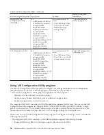
Page 111: ...s to the startup sequence that is set in the Setup Utility Configuring RAID controllers The following table lists the various utilities available to configure RAID controllers before an operating system is installed Table 15 RAID configuration utilities RAID configuration utility Description Location Where to find more information EasyStartup RAID configuration utility v For use with all supported...

Page 112: ...on Utility program Using LSI Configuration Utility program Use the LSI Configuration Utility program to configure and manage redundant array of independent disks RAID arrays Be sure to use this program as described in this document v Use the LSI Configuration Utility program to perform the following tasks Perform a low level format on a hard disk drive Create an array of hard disk drives with or w...

Page 113: ...r is connected to ac power the power control button becomes active 2 When the prompt F1 Setup is displayed press F1 If you have set an administrator password you are prompted to type the password 3 Select System Settings Adapters and UEFI drivers 4 Select Please refresh this page on the first visit and press Enter 5 Select LSI controller_driver_name Driver and press Enter where controller_driver_n...

Page 114: ... turn on the power and when the computer is starting you are prompted to press Ctrl H when the following message is displayed Copyright LSI Logic Corporation Press Ctrl H for WebBIOS 2 Select a controller from the list 3 Click Start The main WebBIOS utility interface is displayed You can toggle between the physical view and logical view of the storage devices that are connected to the controller C...

Page 115: ...ext 4 Select a configuration mode from the following options Custom Configuration In this mode you can control all attributes of the new storage configuration Auto Configuration and Redundancy This mode automatically creates an optimal RAID 1 or RAID 5 configuration providing data redundancy Auto Configuration without Redundancy This mode automatically creates a non redundant RAID 0 configuration ...

Page 116: ...ave time v Creates a reusable response file that can be used with similarly configured Lenovo servers to make future installations even faster Before you use the EasyStartup DVD Functionality and supported operating systems can vary with different versions of the EasyStartup program To learn more about the version you have do the following 1 Insert the EasyStartup DVD and restart the server 2 Adva...

Page 117: ... interface you will have the following selectable options v Compatibility notes This selection provides information about the RAID controllers operating systems and server configurations supported by that version of the EasyStartup program v User Guide This selection provides information about the features provided by that version of the EasyStartup program v Hardware list This selection displays ...

Page 118: ...tware and ThinkServer EasyManage software products v Install Windows components This task enables you to install optional Windows components such as IIS ASP NET and SNMP v Confirm settings This task enables you to review all of the information you provided v Save response file This task gives you the option of saving the information on a diskette or USB device as a response file for future install...

Page 119: ...pdate Firmware Updater tool ThinkServer EasyUpdate Firmware Updater is a software application that enables you to maintain your system firmware up to date and helps you avoid unnecessary outages Firmware Updater updates the server firmware in two steps by updating system firmware adapter firmware and hard disk drive HDD firmware To update your system first go to the Lenovo Support Web site and obt...

Page 120: ...n recover the UEFI firmware using the boot block jumper and a UEFI recovery diskette The system board contains a backup copy area for the server firmware This is a secondary copy of the server firmware that you update only during the process of updating the server firmware If the primary copy of the server firmware becomes damaged use this backup copy To force the server to start from the backup c...

Page 121: ...and power supply failure v DIMM error assistance The Unified Extensible Firmware Interface UEFI disables a failing DIMM that is detected during POST and the IMM lights the associated system error LED and the failing DIMM error LED v System event log SEL v ROM based IMM firmware flash updates v Auto Boot Failure Recovery ABR v A virtual media key which enables remote presence support remote video r...

Page 122: ...r other IMM settings The remote presence features provide enhanced systems management capabilities In addition the ASU program provides limited settings for configuring the IPMI function in the IMM through the command line interface Use the command line interface to issue setup commands You can save any of the settings as a file and run the file as a script The ASU program supports scripting envir...

Page 123: ...g Web site http www microsoft com downloads details aspx FamilyID 1ba1f631 c3e7 420a bc1e ef18bab66122 DisplayLang en Install the software using the default settings Note This specific version is required 5 Use Windows Update to install all available critical updates 6 Launch the EasyManage installation 7 After ThinkServer EasyManage is installed enable Security and Patch Manager to obtain the LAN...

Page 124: ...thout the virtual media key you will not be able to access the network remotely to mount or unmount drives or images on the client system However you can still access the Web interface without the key After the virtual media key is installed in the server it is authenticated to determine whether it is valid If the key is not valid you receive a message from the Web interface when you attempt to st...

Page 125: ...n the next screen select Integrated Management Module 5 On the next screen select Network Configuration 6 Find the IP address and write it down 7 Exit from the Setup utility Logging on to the Web interface To log on to the Web interface to use the remote presence functions complete the following steps 1 Open a Web browser and in the address or URL field type the IP address or host name of the IMM ...

Page 126: ...hat is described in this document 1 Go to http www lenovo com support 2 Enter your product number machine type and model number or select Servers and Storage from the Select your product list 3 From Family list select ThinkServer RS210 and click Continue Enabling and configuring Serial over LAN SOL Establish a Serial over LAN SOL connection to manage servers from a remote location You can remotely...

Page 127: ...v Data Bits 8 v Parity None Stop v Bits 1 v Thermal Emulation ANSI v Active After Boot Enable v Flow Control Hardware d Press Esc twice to exit the Devices and I O Ports section of the Configuration Setup Utility program e Select Save Settings then press Enter f Press Enter to confirm g Select Exit Setup then press Enter h Make sure that Yes exit the Setup Utility is selected then press Enter Chap...

Page 128: ...112 ThinkServer RS210 Types 6531 6532 6533 and 6534 Installation and User Guide ...

Page 129: ...data firmware and UEFI configuration Hard disk drive health RAID controller configuration Controller and service processor event logs including System error logs Temperature voltage and fan speed information Systems management analysis and reporting technology SMART data Machine check registers USB information Video and monitor configuration information Video memory test results PCI slot informati...

Page 130: ...e UEFI Setup Utility program When you are troubleshooting PCI Express slots note that the error logs report the PCI Express buses numerically The numerical assignments vary depending on the configuration You can check the assignments by running the UEFI Setup Utility program Viewing error logs from the UEFI Setup Utility program To view the error logs do the following 1 Turn on the server 2 When t...

Page 131: ...Restart the server If the error is corrected the old microprocessor is bad and must be replaced 3 Replace the following components one at a time in the order shown restarting the server each time a Trained service technician only Microprocessor b Trained service technician only System board 0011000 Invalid microprocessor type 1 Update the server firmware to the latest level see Updating the firmwa...

Page 132: ... the DIMMs 2 Remove and replace any DIMM for which the associated error LED is lit see Replacing or installing a memory module DIMM on page 32 3 Run the Setup utility to enable all the DIMMs 4 Run the DSA Preboot memory test see Diagnostic tools on page 113 0051006 DIMM mismatch detected Make sure that the DIMMs match and are installed in the correct sequence see Installing a memory module on page...

Page 133: ...each pair until a pair fails Replace the DIMMs in the failed pair with identical known good DIMMs restarting the server after each DIMM is installed Replace the failed DIMM Repeat this step until you have tested all removed DIMMs 5 Trained service technician only Replace the system board 0058008 DIMM failed memory test 1 Reseat the DIMMs and then restart the server 2 Replace the following componen...

Page 134: ... might not be initialized 1 If possible rearrange the order of the adapters in the PCI slots to change the load order of the optional device ROM code 2 Run the Setup utility select Startup Options and change the boot priority to change the load order of the optional device ROM code 3 Run the Setup utility and disable some other resources if their functions are not being used to make more space ava...

Page 135: ...tings are used 3048006 Booted secondary backup UEFI image because of ABR 1 Run the Setup utility select Load Default Settings and save the settings to recover the primary UEFI settings 2 Turn off the server and remove it from the power source 3 Reconnect the server to the power source then turn on the server 305000A RTC date time is incorrect 1 Adjust the date and time settings in the Setup utilit...

Page 136: ...ttings Information only This message is usually associated with the CMOS battery clear event 3138002 Boot configuration error 1 Remove any recent configuration changes made to the Setup utility 2 Run the Setup utility select Load Default Settings and save the settings 3808000 IMM communication failure 1 Remove power from the server for 30 seconds and then reconnect the server to power and restart ...

Page 137: ... aborted 1 Run the Setup utility select Load Default Settings and save the settings 2 Trained service technician only Replace the system board 3818003 Core Root of Trust Measurement CRTM flash lock failed 1 Run the Setup utility select Load Default Settings and save the settings 2 Trained service technician only Replace the system board 3818004 Core Root of Trust Measurement CRTM system error 1 Ru...

Page 138: ...king do the following before using the troubleshooting tables 1 Check the system error LED on the operator information panel to see if it is lit 2 Remove the software or device that you just added 3 Run the diagnostic tests to determine whether the server is running correctly 4 Reinstall the new software or new device EasyStartup problems Table 17 EasyStartup DVD v Follow the suggested actions in ...

Page 139: ...er replaceable units CRUs and which components are field replaceable units FRUs v If an action step is preceded by Trained service technician only that step must be performed only by a trained service technician Symptom Action The DVD ROM drive is not recognized 1 Make sure that v The SATA connector to which the DVD drive is attached primary or secondary is enabled in the Setup utility v All cable...

Page 140: ...onents are field replaceable units FRUs v If an action step is preceded by Trained service technician only that step must be performed only by a trained service technician Symptom Action A cover lock is broken an LED is not working or a similar problem has occurred If the part is a CRU replace it If the part is a FRU the part must be replaced by a trained service technician Hard disk drive problem...

Page 141: ... the activity of the LEDs changes return to step 1 4 Make sure that the hard disk drive backplane is correctly seated When it is correctly seated the drive assemblies correctly connect to the backplane without bowing or causing movement of the backplane 5 Reseat the backplane power cable and repeat steps 1 through 3 6 Reseat the backplane signal cable and repeat steps 1 through 3 7 Suspect the bac...

Page 142: ...dicate the same status for the drive complete the following steps a Turn off the server b Reseat the SAS SATA controller c Reseat the backplane signal cable and backplane power cable d Reseat the hard disk drive e Turn on the server and observe the activity of the hard disk drive LEDs 2 See Problem determination tips on page 136 Hypervisor problems v Follow the suggested actions in the order in wh...

Page 143: ...ee POST on page 113 2 If the reset occurs after the operating system starts disable any automatic server restart ASR utilities or ASR devices that may be installed Note ASR utilities operate as operating system utilities and are related to the IPMI device driver If the reset continues to occur after the operating system starts the operating system might have a problem see Software problems on page...

Page 144: ...n the order in which they are listed in the Action column until the problem is solved v See the Hardware Maintenance Manual to determine which components are customer replaceable units CRUs and which components are field replaceable units FRUs v If an action step is preceded by Trained service technician only that step must be performed only by a trained service technician Symptom Action The amoun...

Page 145: ...re listed in the Action column until the problem is solved v See the Hardware Maintenance Manual to determine which components are customer replaceable units CRUs and which components are field replaceable units FRUs v If an action step is preceded by Trained service technician only that step must be performed only by a trained service technician Symptom Action A microprocessor LED is lit during P...

Page 146: ...nnector on the rear of the server 2 Make sure that v The server is turned on If there is no power to the server see Power problems on page 133 v The monitor cables are connected correctly v The monitor is turned on and the brightness and contrast controls are adjusted correctly 3 Make sure that the correct server is controlling the monitor if applicable 4 Make sure that damaged server firmware is ...

Page 147: ...tention Moving a color monitor while it is turned on might cause screen discoloration Move the device and the monitor at least 305 mm 12 in apart and turn on the monitor Notes a To prevent diskette drive read write errors make sure that the distance between the monitor and any external diskette drive is at least 76 mm 3 in b Non Lenovo monitor cables might cause unpredictable problems 2 Reseat the...

Page 148: ... v You followed the installation instructions that came with the device and the device is installed correctly v You have not loosened any other installed devices or cables v You updated the configuration information in the Setup utility Whenever memory or any other device is changed you must update the configuration 2 Reseat the device that you just installed 3 Replace the device that you just ins...

Page 149: ... power control button by using the force power on jumper see System board switches and jumpers on page 20 If the server starts reseat the operator information panel If the problem remains replace the operator information panel 2 Make sure that the reset button is working correctly a Disconnect the server power cords b Reconnect the power cords 3 Make sure that v The power cords are correctly conne...

Page 150: ...ial device problems v Follow the suggested actions in the order in which they are listed in the Action column until the problem is solved v See the Hardware Maintenance Manual to determine which components are customer replaceable units CRUs and which components are field replaceable units FRUs v If an action step is preceded by Trained service technician only that step must be performed only by a...

Page 151: ... solutions to the problem 3 Contact the software vendor Universal Serial Bus USB port problems v Follow the suggested actions in the order in which they are listed in the Action column until the problem is solved v See the Hardware Maintenance Manual to determine which components are customer replaceable units CRUs and which components are field replaceable units FRUs v If an action step is preced...

Page 152: ...e problem is solved when you remove a PCI card from the server but the problem recurs when you reinstall the same PCI card suspect the PCI card if the problem recurs when you replace the PCI card with a different one suspect the riser card If you suspect a networking problem and the server passes all the system tests suspect a network cabling problem that is external to the server Problem determin...

Page 153: ...rs terminators and cabling v Software versions and levels v Diagnostic program type and version level v Configuration option settings v Operating system control file setup See Appendix A Getting help and technical assistance on page 145 for information about calling for service Diagnostic programs and messages The diagnostic programs are the primary method of testing the major components of the se...

Page 154: ... the server is connected to an ac power source but is not turned on provided that the power supply is operating correctly This feature helps you to isolate the problem when the operating system is shut down Note When you disconnect the power source from the server you lose the ability to view the LEDs because the LEDs are not lit when the power source is removed Before you disconnect the power sou...

Page 155: ...ce technician Component LED Description Action DIMM error LEDs A memory DIMM has failed or is incorrectly installed 1 Remove the DIMM that has the lit error LED 2 Reseat the DIMM 3 Replace the following components one at a time in the order shown restarting the server each time a DIMM b Trained service technician only System board Fan error LEDs A fan has failed is operating too slowly or has been...

Page 156: ...r on the system board An additional LED is lit next to a failing PCI slot 1 Check the system event log for information about the error 2 If you cannot isolate the failing PCI card through the LEDs and the information in the system event log remove one PCI card at a time and restart the server after each PCI card is removed 3 If the failure remains go to http www lenovo com support for additional t...

Page 157: ... not flash within 30 seconds of connecting a power flash to the server complete the following steps a Trained service technician only Use the IMM recovery jumper to recover the firmware see System board switches and jumpers on page 20 b Trained service technician only Replace the system board Power supply LEDs The following minimum configuration is required for the DC LED on the power supply to be...

Page 158: ...not lit replace the power supply 3 If the system board error fault LED is lit Trained service technician only replace the system board Typically indicates that a power supply is not fully seated This is a normal condition before turning on the system On Off or Flashing On Faulty power supply Replace the power supply On On Off Normal operation On On On Power supply is faulty but still operational R...

Page 159: ...lly will not occur the next time you run the diagnostic programs Exception If multiple error codes or system board LEDs indicate a microprocessor error the error might be in a microprocessor or in a microprocessor socket See Microprocessor problems on page 129 for information about diagnosing microprocessor problems If the server stops during testing and you cannot continue restart the server and ...

Page 160: ...144 ThinkServer RS210 Types 6531 6532 6533 and 6534 Installation and User Guide ...

Page 161: ...ome with documentation that contains troubleshooting procedures and explanations of error messages and error codes If you suspect a software problem see the documentation for the operating system or program Using the documentation Information about your Lenovo system and preinstalled software if any or optional device is available in the documentation that comes with the product That documentation...

Page 162: ...change without notice If the number for your country or region is not provided contact your Lenovo reseller or Lenovo marketing representative If possible be at your computer when you call Have the following information available v Machine type and model v Serial numbers of your hardware products v Description of the problem v Exact working of any error messages v Hardware and software configurati...

Page 163: ...hasing additional services During and after the warranty period you can purchase additional services such as support for hardware operating systems and application programs network setup and configuration upgraded or extended hardware repair services and custom installations Service availability and service name might vary by country or region For more information about these services go to the Le...

Page 164: ...148 ThinkServer RS210 Types 6531 6532 6533 and 6534 Installation and User Guide ...

Page 165: ...n Lenovo may make improvements and or changes in the product s and or the program s described in this publication at any time without notice The products described in this document are not intended for use in implantation or other life support applications where malfunction may result in injury or death to persons The information contained in this document does not affect or change Lenovo product ...

Page 166: ... CD or DVD drive speed is the variable read rate Actual speeds vary and are often less than the possible maximum When referring to processor storage real and virtual storage or channel volume KB stands for 1024 bytes MB stands for 1 048 576 bytes and GB stands for 1 073 741 824 bytes When referring to hard disk drive capacity or communications volume MB stands for 1 000 000 bytes and GB stands for...

Page 167: ...site at http www lenovo com lenovo environment recycling Esta unidad debe reciclarse o desecharse de acuerdo con lo establecido en la normativa nacional o local aplicable Lenovo recomienda a los propietarios de equipos de tecnología de la información TI que reciclen responsablemente sus equipos cuando éstos ya no les sean útiles Lenovo dispone de una serie de programas y servicios de devolución de...

Page 168: ...contact your local waste disposal facility For Taiwan Please recycle batteries For the European Union Notice This mark applies only to countries within the European Union EU Batteries or packaging for batteries are labeled in accordance with European Directive 2006 66 EC concerning batteries and accumulators and waste batteries and accumulators The Directive determines the framework for the return...

Page 169: ...l interference when the equipment is operated in a commercial environment This equipment generates uses and can radiate radio frequency energy and if not installed and used in accordance with the instruction manual may cause harmful interference to radio communications Operation of this equipment in a residential area is likely to cause harmful interference in which case the user will be required ...

Page 170: ... EG früher 89 336 EWG zur Angleichung der Rechtsvorschriften über die elektromagnetische Verträglichkeit in den EU Mitgliedsstaaten und hält die Grenzwerte der EN 55022 Klasse A ein Um dieses sicherzustellen sind die Geräte wie in den Handbüchern beschrieben zu installieren und zu betreiben Des Weiteren dürfen auch nur von der Lenovo empfohlene Kabel angeschlossen werden Lenovo übernimmt keine Ver...

Page 171: ...er Genehmigung des Bundesministers für Post und Telekommunikation oder des Bundesamtes für Post und Telekommunikation betrieben werden Die Genehmigung wird erteilt wenn keine elektromagnetischen Störungen zu erwarten sind Auszug aus dem EMVG Paragraph 3 Abs 4 Dieses Genehmigungsverfahren ist nach Paragraph 9 EMVG in Verbindung mit der entsprechenden Kostenverordnung Amtsblatt 14 93 kostenpflichtig...

Page 172: ...Taiwanese Class A warning statement 01 156 ThinkServer RS210 Types 6531 6532 6533 and 6534 Installation and User Guide ...

Page 173: ...Chinese Class A warning statement Korean Class A warning statement Appendix B Notices 157 ...

Page 174: ...158 ThinkServer RS210 Types 6531 6532 6533 and 6534 Installation and User Guide ...

Page 175: ...32 removing 35 display problems 130 DMI SMBIOS data updating 86 documentation DVD 2 drive cage replacing 55 drives 8 DVD cable installing 80 removing 80 replacing 80 DVD drive installing 46 problems 123 removing 45 replacing 45 Dynamic System Analysis Preboot Diagnostics DSA program 9 E EasyStartup using 100 electrical input 11 environment 11 error codes and messages diagnostic 143 messages diagno...

Page 176: ...key virtual media 8 keyboard problems 127 L LED Ethernet activity status 15 Ethernet link status 15 for CD RW DVD drive activity 14 for hard disk drive activity 14 for hard disk drive status 14 integrated management module 140 power on 13 power on button 14 system locator 14 system error 14 LED Battery failure 139 H8 heartbeat 140 IMM heartbeat 140 System board error 139 LEDs front 13 on the syste...

Page 177: ...iser card power cable 83 power supply 64 SAS SATA backplane 72 SAS SATA backplate 72 system board 62 USB embedded hypervisor flash device 52 virtual media key 82 replacing CRUSs 51 reset button 14 riser card installing 76 removing 43 replacing 76 slots 18 riser card assembly installing 76 location 51 S SAS backplane installing 75 removing 74 SAS SATA backplane installing 72 removing 72 replacing 7...

Page 178: ... connector 14 15 user password 93 See power on password using EasyStartup 100 LSI Configuration program 96 the boot manager program 95 the remote presence feature 108 Utility program IBM Advanced Settings 106 Utility Setup menu choices 90 starting 90 V video connector rear 15 video controller integrated specifications 11 virtual media key installing 82 removing 82 replacing 82 virtual media key su...

Page 179: ......

Page 180: ...Printed in USA ...

Reviews: