


-20-
HYDROCTROL-IOM-1903-E
OPERATING
To change the net settings follow these instructions:
1)
Touch the field which has to be changed
2)
Change the “Auto” mode to manual by touching the Auto button:
3)
Touch the writing field and use the keypad to enter the new value
4)
Repeat the action 1 to 3 for all the field you have to change
5)
Once new values are written touch the set button
6)
Wait 10 seconds and reset all field to auto value by touching the field
and then touching the manual button. /!\ do not change the value
7)
Press enter to validate
If the value remains the same, the HMI did correctly take in count the new
network parameters
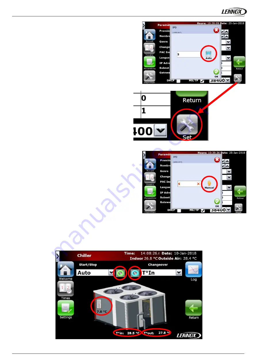
Chiller screens
The chiller screens are available only if the chiller option is set (see HYDROCONTROL start up paragraph). To access the chiller
screen click on the chiller button from the home page (see HYDROCONTROL home page paragraph).
1
2
3
4
5
Picture28: Editing pop up (Auto)
Picture29: Set IP modification
Picture30: Editing pop up (Manual)
Picture31: Chiller main screen


