background image


Page 56 of 61 

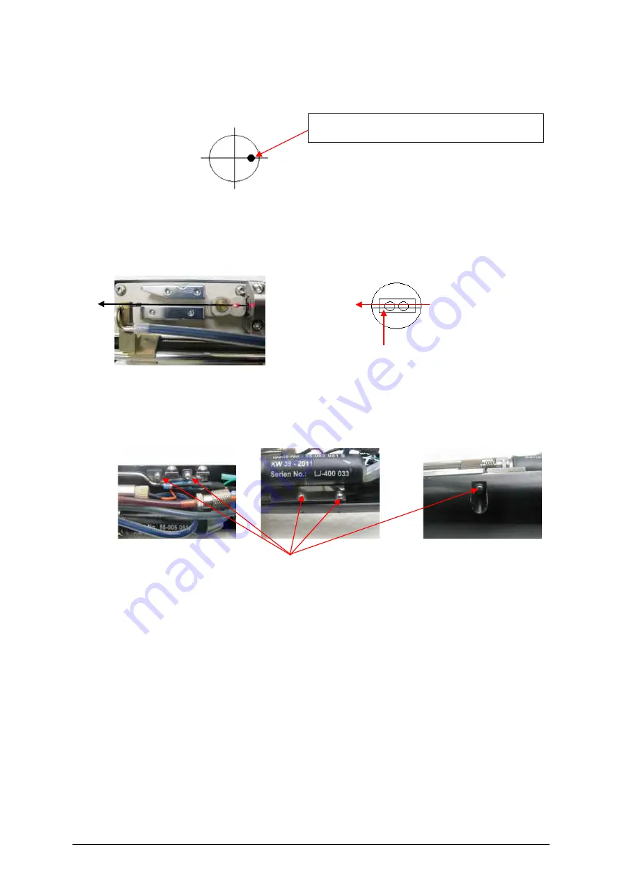
6.  Adjust the ink jet just like in the sketch below. The sketch shows the view from nozzle to gutter. 

The ink jet is adjusted by moving the oscillator body, which is connected, to the nozzle retainer. 

See picture above. When the ink jet is in the correct position, fix the screws again. 


7.  After the ink jet adjustment, it may be necessary to adjust the entire drop production unit in order 

to make sure that the ink jet passes in parallel to the inner edges of the charging tunnel. To avoid 

parallax faults you need to point your perspective exactly vertical to the charging tunnel. 


inner edge of the charging tunnel 


8.  To adjust the drop production unit you need to untighten the five attachment screws of the fixing 

plate just so far that you can move the unit manually. After adjusting the unit, fix the attachment 

screws and check the position of the ink jet. 


Ink jet position in gutter tube 

Attachment screws 

Summary of Contents for JET Rapid

Page 1: ...Technical information The new LEIBINGER High Speed Line Version 2 4 ...

Page 2: ...Page 2 of 61 ...

Page 3: ...d with beveled design 17 3 3 General technical specifications JET Rapid Wire JET Rapid Wire PI 18 3 3 1 Overview JET Rapid Wire 18 3 3 2 Overview JET Rapid Wire PI 18 3 4 Basic parameters for Print height Stroke distance and Speed 19 3 4 1 JET Rapid Wire with Wire print head and stepped print head cover 20 3 4 2 JET Rapid Wire with Wire print head and beveled print head cover 20 3 4 3 JET Rapid Wi...

Page 4: ...s 37 7 1 2 3 Available print modes for the JET Rapid Wire Rapid Wire PI 38 7 2 JET Rapid Wire Rapid Wire PI JET Rapid with option Speed Plus Print head adjustments and exchange of print head parts 39 7 2 1 Adjustment of the Ink jet position inside the gutter tube 39 7 2 2 Adjustment of the drop production unit 44 7 2 3 Adjusting the distance between ink jet and ink drop voltage detector 48 7 2 4 E...

Page 5: ...ond chapter provides information about the JET Rapid Wire printer Important Information There are several significant differences between the JET3up and the printers of the JET Rapid series The differences affect parts of the printer as well as service procedures It is highly recommended thoroughly checking the manuals and the accessories catalogue for the differences between the JET3up and the JE...

Page 6: ...ficient If for instance a print job for the JET3up printed with the 32 dot high quality print mode allows a printing speed of 30 meter minute it will be possible to print the same job with the JET Rapid at a speed of around 40 m min In order to reach a good quality for the printouts at the faster speeds the recommended distance between print head and substrate is 15 mm The print head of the JET Ra...

Page 7: ...in smaller drops and the substrate will not absorb all drops With a vertically mounted print head the bursting ink drops may lead to a faster contamination of the print head With the beveled surface of the outlet of the print head it is possible to mount the print head in a slightly inclined position The ink drops will not hit the substrate at a 90 angle Therefore the bursting ink drops will take ...

Page 8: ...e Yes 2 l min 2 4 Basic parameters for Print height Stroke distance and Speed 2 4 1 JET Rapid The JET Rapid provides the same print modes as the JET3up The recommended printing distance is 15mm There are no special recommendations regarding the settings for the print height The print mode selected has a direct effect on the maximum printing speed However the JET Rapid provides a 30 higher printing...

Page 9: ...al printing speed will cause StrokeGo errors A value too large may have a negative effect on the quality of the printout The values in the table are minimum values for the corresponding print modes and speeds For instance Working with the 5x5 dots print mode the minimum value for the stroke distance at a speed of 800 m min is 0 62 mm For the same print mode at a speed of 260 m min the minimum stro...

Page 10: ... 0 3 0 52 580 800 3x7 dots tower 1 6 2 4 mm 70 100 PH 0 3 0 52 580 800 5x5 dots small speed 1 5 1 8 mm 80 100 PH 0 2 0 52 260 800 5x5 dots small 1 5 1 8 mm 80 100 PH 0 2 0 52 260 800 5x5 dots 1 7 2 1 mm 80 100 PH 0 2 0 52 260 800 5x5 dots speed 1 7 2 1 mm 80 100 PH 0 2 0 52 260 800 7x5 dot Speed 2 1 2 4 mm 80 100 PH 0 25 0 52 240 500 7x5 dot 2 1 2 4 mm 80 100 PH 0 25 0 52 240 500 Full stroke with ...

Page 11: ...trictions There is a smaller range of approved inks available than for the JET3up For optimal results the recommended distance between print head and substrate 15 mm Shorter distances bear the risk of contaminating the print head larger distances may have a negative effect on the quality of the printouts Single line printing There is a smaller range of approved inks available than for the JET3up R...

Page 12: ...s The print samples show that the JET Rapid provides the same print quality as the JET3up but at a 30 higher production speed The printouts of the JET Rapid are a shade lighter than the printouts of the JET3up However a quality check of the 2 D code shows that the code has the highest readability level JET Rapid 55 µm nozzle 28 m min JET3up 60 µm nozzle 20 m min PQA print quality assessment for th...

Page 13: ...zontal Print Growth 3 of X A Vertical Print Growth 10 of X The PQA show the highest readability for the printouts of a JET Rapid with the small drop ink 70000 00031 The smaller nozzle size combined with a small drop ink has no significant effects on the Print Quality Assessment PQA 2 6 3 Print samples JET Rapid in comparison with the option SPEED PLUS The print samples show that with a 7x5 font th...

Page 14: ...s in size Data Field 12 data 12 chks in 1 block s of GF 256 X roughly 0 019 A Fixed Patterns 0 module errors A Data Safety Margin 100 A Horizontal Print Growth 14 of X A Vertical Print Growth 4 of X The PQA does not show any significant differences between the code readability of the two printouts 2 6 5 Print sample JET Rapid with 70000 00031 ink The print samples show that even with a small drop ...

Page 15: ...tions at 30 more speed Multi line print Same print modes like JET3up Larger drops higher contrast JET3up RAPID 55 µm Nozzle 128 kHz drop frequency Ink list RAPID Printing speed 30 faster than JET3up SK6 print head SK6 Print head cover 70 030 70 031 70 101 70 106 70 126 70 134 72 102 76 101 Option Speed 50 µm Nozzle 128 kHz drop frequency Ink list Option SPEED Up to 800 m min printing speed SK6 HS ...

Page 16: ...ds Due to its design the print head is applicable for wires cables or tubes with a diameter smaller than 5 mm The stepped print head cover designed for printing on wires cables or tubes with diameters 5mm at high speeds The illustrations show the special Wire print head with a stepped print head cover and wires of different diameters It is important to get the wire respectively the print head in a...

Page 17: ...drops may lead to a faster contamination of the print head With the beveled surface of the outlet of the print head it is possible to mount the print head in a slightly inclined position The ink drops will not hit the substrate at a 90 angle Therefore the bursting ink drops will take a direction away from the outlet which will lead to less contamination of the print head Generally With the beveled...

Page 18: ... for a detailed ink list Please see appendix for a detailed ink list Compressed air required Yes 2 l min Yes 2 l min 3 3 2 Overview JET Rapid Wire PI Wire printhead with stepped head cover Wire printhead with beveled head cover Print head Wire Wire Print head dimensions Maximum printing speed 700 m min 600 m min Characters per inch cpi 7 cpi at 700 m min Print mode 5x5 dot speed 8 cpi at 600 m min...

Page 19: ...the stroke distance has to correspond with the maximum speed that is expected for the job A value too small for the actual printing speed will cause StrokeGo errors A value too large may have a negative effect on the quality of the printout The values in the table are minimum values for the corresponding print modes and speeds For instance Working with the 5x5 dots print mode the minimum value for...

Page 20: ...9 0 39 240 500 7x5 dot 1 7 2 0 mm 80 100 PH 0 22 0 52 240 500 Full stroke with 4 dots Full stroke with 6 dots 3 4 2 JET Rapid Wire with Wire print head and beveled print head cover Print mode Height mm Print height setting PH Recommended stroke distance mm Speed m min 1 dot Line mode 100 PH 0 15 0 29 580 800 3x7 dots tower small 1 2 1 7 mm 70 100 PH 0 3 0 42 580 800 3x7 dots tower 1 6 2 4 mm 70 10...

Page 21: ...60 600 7x5 dot Speed 1 9 2 2 mm 90 100 PH 0 19 0 31 240 400 7x5 dot 1 9 2 2 mm 90 100 PH 0 22 0 37 240 400 Full stroke with 4 dots Full stroke with 6 dots 3 4 4 JET Rapid Wire PI with Wire print head and stepped print head cover Print mode Height mm Print height setting PH Recommended stroke distance mm Speed m min 1 dot Line mode 80 100 PH 0 15 0 16 580 600 3x7 dots tower small 1 2 1 7 mm 70 100 ...

Page 22: ...ed printing with a maximum print height of 2 5 mm Restrictions Only 1 print line There is a smaller range of approved inks available than for the JET3up There are 7 print modes available o 1 dot o Line mode o 3x7 dots tower small o 3x7 dots tower o 5x5 dots small speed o 5x5 dots small o 5x5 dots o 5x5 dots speed o 7x5 dots o 7x5 dots speed The diameter of the substrate must not be larger than 5 m...

Page 23: ...ting with pigmented ink on cables wires tubes with diameters larger than 5 mm High speed printing with a maximum print height of 2 4 mm Restrictions Only 1 print line There is a smaller range of approved inks available than for the JET3up There are 7 printmodes available o 1 dot o Line mode o 3x7 dots tower small o 3x7 dots tower o 5x5 dots small speed o 5x5 dots small o 5x5 dots o 5x5 dots speed ...

Page 24: ...tion must not exceed 7 C based on the ink temperature at the time of the last calculation of the drop break off point whereby the ink temperature should never fall below 20 C and never exceed 45 C 3 7 Cleaning requirements Due to their compositions some inks have limitations with regards to their cleaning intervals Especially inks that contain soot particles also require a more intensive cleaning ...

Page 25: ... 8 1 Print samples JET Rapid Wire Not available at the moment 3 8 2 Print samples JET Rapid Wire in comparison with JET Rapid The print sample show that with a 7x5 font the JET Rapid Wire has quality advantages compared with the JET Rapid at speed higher than 200 m min JET Rapid Wire 200 m min JET Rapid 200 m min JET Rapid Wire 300 m min JET Rapid 300 m min JET Rapid Wire 400 m min JET Rapid 400 m...

Page 26: ...d Wire a printer at 800 m min with the beveled print head and at 1000 m min with the stepped print head Printout JET Rapid Wire 1000 m min 3x7 tower font full printout Printout JET Rapid Wire 1000 m min 3x7 tower font details Printout JET Rapid Wire 800 m min 5x5 font full printout Printout JET Rapid 800 m min 5x5 font details ...

Page 27: ...rint modes available are restricted to small size matrixes 3x7 tower 4x5 5x5 7x5 These print modes are good for small size characters to be printed at high speeds up to 1000 m min The JET Rapid is a good choice for applications for which the JET3up is not fast enough for the printout quality required The JET Rapid provides the same print modes as the JET3up but it is possible to work at speeds tha...

Page 28: ...ozzle 128 kHz drop frequency Ink list JET Rapid Printing speed 30 faster than JET3up Rapid print head SK6 Print head cover 70 030 70 031 70 101 70 106 70 126 70 134 72 102 76 101 Option Speed Plus 50 µm Nozzle 128 kHz drop frequency Ink list Option Speed Plus Up to 800 m min printing speed Speed Plus print head Beveled print head cover 70 106 70 126 70 134 72 102 76 101 Exclusively for cable print...

Page 29: ...e head ventilation there is a constant air stream at the outlet of the print head that works like a protective shield against the remains of ink droplets that burst on the surface of the substrate Example print head ventilation with the JET Rapid Wire The print head of the JET Rapid Wire during the printing process The ink jet is illustrated as a series of red droplets With the JET Rapid Wire the ...

Page 30: ...e and JET Rapid Wire PI with stepped or beveled print head cover 2 l min for JET Rapid with option Speed Plus Warning Operation is only permissible with clean dry oil free and filtered compressed air Filtering 8 μm Using compressed air that does not meet these requirements may cause serious damages to the print head Attention Make sure that there is a permanent compressed air supply o The printer ...

Page 31: ...the axis of the encoder The given circumference of the measuring wheel and the resolution of the encoder results in the pulses per mm 𝑛𝑛𝑛𝑛𝑛𝑛𝑛𝑛𝑛𝑛𝑛𝑛 𝑜𝑜𝑜𝑜 𝑝𝑝𝑝𝑝𝑝𝑝𝑝𝑝𝑝𝑝𝑝𝑝 𝑝𝑝𝑝𝑝𝑝𝑝 𝑟𝑟𝑟𝑟𝑟𝑟𝑟𝑟𝑟𝑟𝑟𝑟𝑟𝑟𝑟𝑟 𝐶𝐶𝐶𝐶𝐶𝐶𝐶𝐶𝐶𝐶𝐶𝐶𝐶𝐶𝐶𝐶𝐶𝐶𝐶𝐶𝐶𝐶𝐶𝐶𝐶𝐶 𝑚𝑚𝑚𝑚𝑚𝑚𝑚𝑚𝑚𝑚𝑚𝑚𝑚𝑚𝑚𝑚𝑚𝑚 𝑤𝑤ℎ𝑒𝑒𝑒𝑒𝑒𝑒 𝑚𝑚𝑚𝑚 𝑝𝑝𝑝𝑝𝑝𝑝𝑝𝑝𝑝𝑝𝑝𝑝 𝑚𝑚𝑚𝑚 If for instance the circumference of the measuring wheel is 200 mm the resolution is 2 500 200 𝑝𝑝𝑝𝑝𝑝𝑝𝑝𝑝𝑝𝑝𝑝𝑝 𝑚𝑚𝑚𝑚 12 5 𝑝𝑝𝑝𝑝𝑝𝑝𝑝𝑝𝑝𝑝𝑝𝑝 𝑚...

Page 32: ...channel B HTL 24V F encoder channel B RS422 M PowerOn Option Signal Parameter Value RS422 Input level Differential 200mV Input voltage range 0 3 to 5 5V Max frequency 10 MHz Terminating resistance 120 Ohm TTL Input level high 2 4V to 5 5V Input level low 0 5V to 0 7V Max frequency 500 kHz Input resistance 1 MOhm HTL Input level high 12 to 28V Input level low 0 5 to 3 5V Max frequency 500 kHz Input...

Page 33: ...𝑘 Therefore at the maximum speed permitted mechanically the output frequency stays below the 300 kHz allowed How to calculate the actual output frequency In order to calculate the actual number of revolutions per minute the following parameters are required The resolution per rotation of the encoder The circumference of the measuring wheel that is used The maximum production speed This example cal...

Page 34: ...fic ink types tested and approved for the JET Rapid printer series and for these inks the operator will find default settings in the hydraulic menu For inks that are not approved there are no default settings available Attention Using an ink that is not approved for high speed printing may result in printouts of dissatisfying quality Additionally an ink that is not approved may cause serious issue...

Page 35: ... the dialog box The appropriate default values for o Max Frequency KHz o Pressure mbar and o Fall Time msec are displayed on the right side of the dialog box in the same line as the corresponding input field 3 The settings are confirmed with a click on the button Yes Confirm the settings With an unapproved ink X The ink 70000 00105 is not approved for the JET Rapid printer With this ink selected n...

Page 36: ...e JET Rapid The following steps show how to get to the Printstyle tab in the Job settings dialog box Select Settings in the menu of the job editor and then select the Printstyle tab Information The available print modes for the JET Rapid are the same as for the JET3up For the JET Rapid are the same print modes available as for the JET3up ...

Page 37: ...tab in the Job settings dialog box Select Settings in the menu of the job editor and then select the Printstyle tab Information Depending on the selected oscillator frequency a different number of print modes are available Oscillator frequency 128 KHZ Nozzle size 50 µm 9 Printmodes available The 9 print modes of the JET Rapid with the option Speed Plus ...

Page 38: ...ngs dialog box Select Settings in the menu of the job editor and then select the Printstyle tab Information Depending on the selected oscillator frequency a different number of print modes are available Oscillator frequency 128 KHZ Nozzle size Rapid Wire 50 µm Rapid Wire PI 60 µm 9 Printmodes available The 9 print modes of the JET Rapid Wire Rapid Wire PI ...

Page 39: ...re evident signs of a misadjustment like a contamination of the gutter with ink Adjustment of the drop production unit The adjustment of the drop production unit is necessary after a disassembled print head was reassembled This is not a standard procedure You must not change the adjustment if the print head was not disassembled Exchange of the oscillator describes the removal and the mounting of t...

Page 40: ...ad 2 Turn off the function Ink Flow Sensor 3 1 Softkey Hydraulik settings 2 Menu Print head 3 Button Ink Flow Sensor 3 Use the hex key to untighten the mounting screws of the cover You do not have to remove the screws Untighten the mounting screws Do not remove them Remove the cover 2 1 3 ...

Page 41: ...tention Use the T6 torx only Unloose the fixing A screw using a T6 Fixing screw B Attention The two adjusting screws 1 and 2 are only for the fine adjustment If the drop production unit is completely misaligned you must additionally untighten the fixing screw B and perform a rough adjustment by moving the complete drop production unit For a first rough adjustment or if the adjusting screws A and B...

Page 42: ...al direction during the adjustment procedure will not have an immediate effect Instead it takes some turns of the screw until the jet moves Example Turn screw 2 clockwise to adjust the ink stream to the right side When you change to counter clockwise turns it will take a few turns until the jet position actually reacts The same is true for the up down adjustment with screw 1 You must not tighten t...

Page 43: ...e Correct adjustment Incorrect adjustment Incorrect adjustment 7 When finished refasten the mounting screws and check the correct ink jet position Attention Use the T6 torx only Correct ink jet position inside the gutter tube The ink jet should be as close as possible ca 90 to the outer edge of the gutter tube The ink jet position inside the gutter tube is too far in the middle The ink jet positio...

Page 44: ...harging tunnel and deflecting plates The ink jet has to pass in parallel to the inner edges of the charging tunnel To avoid parallax errors you need to point your perspective exactly vertically above the charging tunnel Top view 1 The charging tunnel 2 The inner edge of the charging tunnel Information During the adjustment of the swivel mechanic in step 2 you should also check the ink jet position...

Page 45: ...k jet Insert the 0 1 mm blade between the drop production unit and the charging electrode Attention Take care that the nozzle is not covered by the blade so that the ink stream is not affected Optimal adjustment It should be easily possible to insert the blade of the feeling gauge without clearance The swivel mechanic should work without touching the block of the charging electrode 3 During the ad...

Page 46: ...e charging tunnel 2 Ink jet at the inner edge of the charging tunnel 1 Button Ink Flow Sensor active 2 Button Jet Adjust Now open the nozzle seal completely using the arrow key 1 Check the ink jet again Now the Ink stream must be in the middle of the charging tunnel and parallel to the deflecting plates Top view 1 The charging tunnel 2 Ink jet in the middle of the charging tunnel Important It may ...

Page 47: ...ting screws Then recheck the position of the ink jet 6 Close the nozzle seal and mount the cover Attention Be careful not to damage any tubes or cables Reassemble the cover and fix the mounting screws 7 Open the nozzle seal again and control the Ink stream position again to finish the adjustment ...

Page 48: ...hanging defective parts Do not carry out these steps for a standard ink jet adjustment Remove the head cover Use the hex key to untighten the mounting screws of the cover You do not have to remove the screws The optimal distance between ink jet illustrated as blue dotted line and the surface of the ink drop voltage detector is the half of the height H 2mm of the charging tunnel 1 mm Use the set sc...

Page 49: ... the ink drop voltage detector Optimum D Half of the height H 1 8 mm of the charging tunnel 0 8 mm Fix the inside cover again and put on the head cover Attention Be careful not to damage any tubes or cables H 1 8 mm Charging tunnel Voltage detector Ink jet D H 2 0 8 mm ...

Page 50: ...io torque tool Art Nr 55 004557 K Torx T6 Art Nr 55 006360 K Special inlet for oscillator Art Nr 55 006012 S Slotted screwdriver Tweezers Hex key 1 5mm Hex key 2mm Special tool for nozzle Art Nr E55 005548 S Attention Before starting the work open the nozzle to the position Jet adjust Only in this position it is possible to untighten the fixing screw of the nozzle retainer 1 Open the hydraulic dia...

Page 51: ... Loose the retaining screws with a 2mm hex key around one turn and remove the inner head cover 5 Pull out the coax connector of the oscillator by using the tweezers Remove the retaining screw of the grounding cable Keep this screw in save place ...

Page 52: ...e old drop production body 8 Mount the new drop production body back on the adapter of the ground plate 9 Mount screw 2 first then screw 2 10 Please note Do not tighten the screws First the drop production body has to adjusted in a correct position Mount the new drop production body back on the adapter of the ground plate Mount screw 2 first Mount screw 1 1 2 2 1 ...

Page 53: ...duction unit has to be positioned in alignment with the notch on the nozzle retainer When the position is correct tighten screw 1 with a torque of 0 4 Nm Then hand tighten screw 2 12 Screw the grounding cable back to the ground plate Plug in the coax cable Tighten the grounding cable back on the ground plate Plug in the coax cable 13 Finally adjust the ink jet see chapter 7 2 1 Adjustment of the I...

Page 54: ...ter tube JET Rapid Required tools o Sixfold magnifier o 2mm hex key o T6x50 torx 1 Switch on the JET Rapid and wait while the system is bleeding 2 Touch the soft key Hydraulic settings 1 and change to the menu Print head 2 Turn off the function Ink Flow Sensor 3 1 Softkey Hydraulic settings 2 Menu Print head 3 Button Ink Flow Sensor 2 1 3 ...

Page 55: ...t arrow button in order to open the nozzle 2 completely The Rapid print head with the nozzle opened 1 Tab Print head 2 Arrow Button for opening the nozzle 5 Untighten the right attachment screw see picture below of the nozzle retainer just so far that you can adjust the retainer manually For a better movability It may be necessary to untighten the other screw as well Attention Use the T6 torx only...

Page 56: ...e entire drop production unit in order to make sure that the ink jet passes in parallel to the inner edges of the charging tunnel To avoid parallax faults you need to point your perspective exactly vertical to the charging tunnel inner edge of the charging tunnel 8 To adjust the drop production unit you need to untighten the five attachment screws of the fixing plate just so far that you can move ...

Page 57: ...allel to the inner edges of the tunnel 1 Button Ink Flow Sensor 2 Button arrow Important It may happen that you have to re adjust the drop production unit again after adjusting the ink jet Both procedures affect each other 10 Close the nozzle seal and fix the inside cover Attention Be careful not to damage any tubes or cables 11 Open the nozzle seal again and check the ink jet position to finish t...

Page 58: ...ry tools Vario torque tool Art Nr 55 004557 K Torx T6 Art Nr 55 006360 K Special inlet for oscillator SK6 Art Nr 55 006012 S Slotted screwdriver Tweezers Hex key 1 5mm Hex key 2mm Special tool for nozzle SK6 Art Nr E55 005548 S 1 Switch on JET Rapid and wait until bleeding is finished ...

Page 59: ...f 4 and Jet adjust 5 1 Button Hydraulic settings 2 Menu Hydraulic 3 Menu Printhead 4 Button Ink off 5 Button Jet Adjust 4 Remove the print head head cover Untighten the retaining screws with a 2mm hex key by one turn and remove the inner head cover 5 Dismantle the nozzle Please see the respective service documentation for details 1 2 3 4 5 ...

Page 60: ...tweezers Screw out the retaining screw of the grounding cable 7 Remove the retainer of the tubus after removing the two torx screws 8 Push the drop production body slightly to the side and remove the oscillator with the special tool Clean the drop production body with solvent ...

Page 61: ... be positioned correctly Use the markings There is a slot in the drop production body and also in the adapter Both slots result in one long slot when the drop production body is in the right position 11 Tighten the grounding cable back on the ground plate Plug in the coax cable 12 Mount the nozzle back in the drop production body Please see the respective service documentation for details 13 Final...

Reviews: