background image

Model 831 Manual

1/1 and 1/3 Octave Filters

A-23

1/1 Octave Filter Linearity

The filter linearity range depends upon both the Input Gain, which is set as described in the section "20
dB Gain" on page 4-5,
 and the Filter Range, which is set as described in the section "OBA Range
Setting" on page 4-7.The dat
a, which were measured using an electrical input, are in dB re. 1 

V,

which is equivalent to dBSPL when a 50 mV/Pa microphone is used

Table A-20  1/1 Octave Linearity Range

1/1 Octave Filter Summation Error

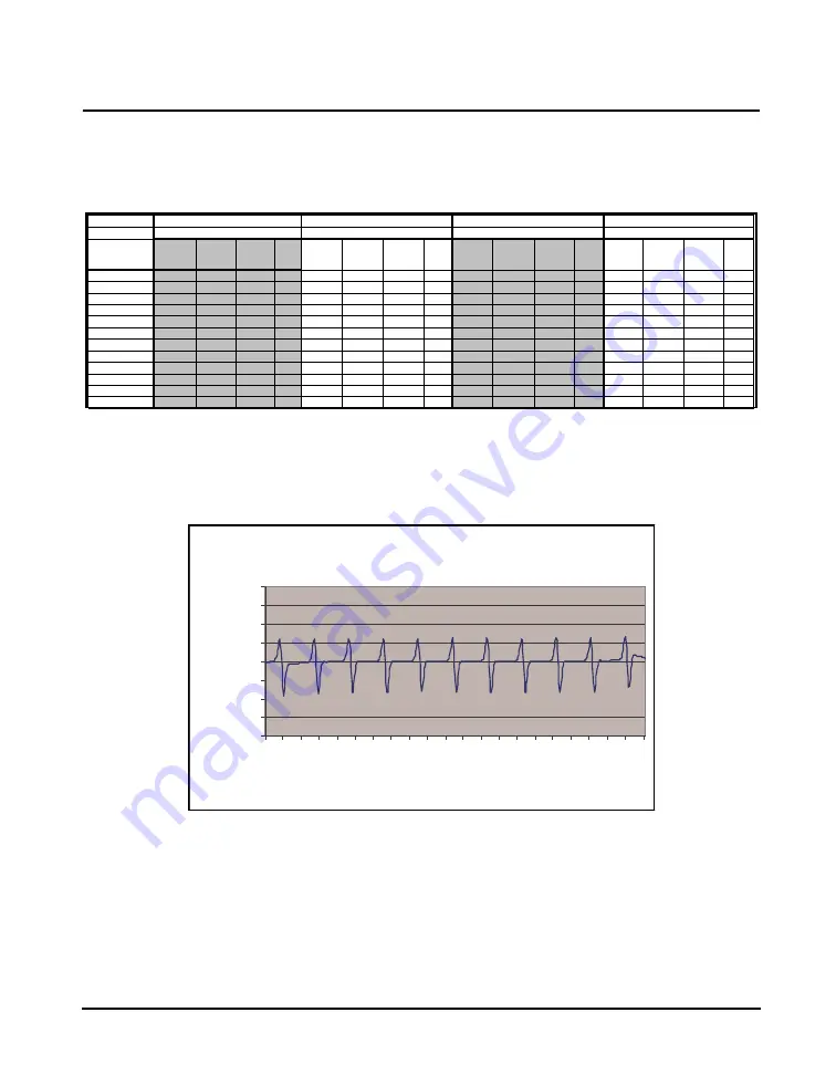
The Octave Filter Summation Error shown in the following graphs is defined by IEC61260 4.9.

FIGURE A-4  Gain = 0 dB, Filter Range = Normal

Gain

0 dB

0 dB

20 dB

20 dB

Range

Normal

Low

Normal

Low

Frequency

Overload

Linearity 
Range

Lower 
Linearity 
Limit

Noise 
Floor

Overload

Linearity 
Range

Lower 
Linearity 
Limit

Noise 
Floor

Overload

Linearity 
Range

Lower 
Linearity 
Limit

Noise 
Floor

Overload

Linearity 
Range

Lower 
Linearity 
Limit

Noise 
Floor

8.0

140.8

78.9

61.9 31.9

107.5

75.5

32.0

14.1

120.7

83.7

37.0

16.2

87.4

52.4

35.0

13.7

16.0

140.8

85.8

55.0 31.9

107.5

78.7

28.8

12.8

120.7

88.7

32.0

14.7

87.4

59.4

28.0

10.0

31.5

140.8

87.8

53.0 30.4

107.5

80.5

27.0

8.8

120.7

89.7

31.0

14.3

87.4

58.4

29.0

9.0

63.0

140.8

92.8

48.0 29.5

107.5

81.5

26.0

6.2

120.7

90.7

30.0

12.9

87.4

60.4

27.0

5.8

125.0

140.8

95.8

45.0 31.1

107.5

84.5

23.0

4.4

120.7

89.7

31.0

12.6

87.4

65.4

22.0

4.1

250.0

140.8

94.8

46.0 31.1

107.5

90.5

17.0

2.2

120.7

92.7

28.0

11.2

87.4

70.4

17.0

2.8

500.0

140.8

90.8

50.0 33.5

107.5

92.5

15.0

2.1

120.7

91.7

29.0

12.1

87.4

69.4

18.0

2.0

1000.0

140.8

95.7

45.1 31.7

107.5

88.5

19.0

2.0

120.7

95.7

25.0

12.0

87.4

70.4

17.0

0.2

2000.0

140.8

92.7

48.1 33.6

107.5

92.5

15.0

2.5

120.7

95.6

25.1

13.8

87.4

75.4

12.0

-2.9

4000.0

140.8

90.8

50.0 36.7

107.5

90.5

17.0

5.1

120.7

92.6

28.1

16.7

87.4

77.4

10.0

-2.3

8000.0

140.8

88.8

52.0 40.3

107.5

87.5

20.0

8.3

120.7

87.7

33.0

20.2

87.4

75.4

12.0

-0.4

16000.0

140.8

85.8

55.0 43.6

107.5

84.5

23.0

11.5

120.7

85.7

35.0

23.5

87.4

73.4

14.0

2.0

1/1 Octave Sum m ation

(UURU

-2

-1.5

-1

-0.5

0

0.5

1

1.5

2

8.058 18.84 44.03 102.9 240.6 562.3 1314 3073 7182

Frequency

S

u

mma

ti

o

n

(UURU

 (d

B

)

Summary of Contents for 831

Page 1: ...Model 831 Sound Level Meter Manual...

Page 2: ...I831 01 Rev O Manual Larson Davis Model 831 Manual...

Page 3: ...This publication may contain inaccuracies or typographical errors PCB Piezotronics Inc will periodically update the material for inclusion in new editions Changes and improvements to the information d...

Page 4: ...Disconnecting the Preamplifier 2 4 Powering the Model 831 2 4 Chapter 3 Overview 3 1 831 Components 3 1 Summary of Displays and Icons 3 7 Navigating and Selecting 3 12 Basic Run Functions 3 12 Tab an...

Page 5: ...rming the Measurement 7 5 Storing the Measurement 7 15 Recovery After Improper Shutdown 7 17 Chapter 8 Calibration 8 1 Calibration Overview 8 1 Control Panel Calibrate 8 2 Acoustic Calibration 8 5 Sen...

Page 6: ...igger Method 13 3 Event Time History Setup 13 10 Event History Display 13 12 Link to Time History and Measurement History 13 22 Chapter 14 FFT and Tonality 14 1 Accessing FFT Mode 14 1 Configuring a M...

Page 7: ...plorer 17 1 Data Explorer 17 2 Chapter 18 System Properties 18 1 Control Panel System Properties 18 1 Device 18 2 Time 18 3 Power 18 5 Preferences 18 10 Localization 18 20 Displays 18 23 Options 18 29...

Page 8: ...m Utilities 23 1 File System 23 2 Chapter 24 Parameters Measured 24 1 Basic Sound Level Measurements 24 1 Sound Exposure Metrics Measured 24 3 Statistical Metrics Measured 24 4 Exceedance Counters 24...

Page 9: ...1 Model 831 Specifications A 2 CE Information A 20 1 1 and 1 3 Octave Filters A 21 Position of Instrument and Operator A 30 Frequency Response A 32 Vibration Sensitivity A 62 Appendix B Measuring to I...

Page 10: ...driven user interface Quiet Touch elastomeric keypad Large dynamic range 120 dBA RMS Detectors Slow Fast Impulse RMS Frequency Weighting A C Z Peak Frequency Weighting A C Z Any LevelTM Simultaneous...

Page 11: ...Basic Measurements SPL Leq Lmax Lmin Lpeak Lpeak max 2 RMS event counters and 3 Peak event counters LN statistics computed to 0 01 with 0 1 dB accuracy over the range L0 01 through L99 99 with display...

Page 12: ...son Davis via the Internet Purchase Required Options Real time 1 1 1 3 Octave Frequency Analysis 831 OB3 Measurement History for the manual or timed storage of statistical data 831 ELA Automatic Data...

Page 13: ...one 50 mV Pa providing performance conforming to Class 1 sound level meter standards or 377C20 1 2 random incidence pre polarized microphone 50 mV Pa providing performance conforming to Class 1 sound...

Page 14: ...Preamplifiers 1 2 ICP Low Noise Microphone Preamplifier requires adaptor ADP074 PRM2103 Outdoor Microphone Preamplifier PRM426A12 Outdoor Microphone Preamplifier 426A12 NPT Coupler 1 5 X27 ISO228 1 t...

Page 15: ...re NMS017 Permanent noise monitoring system with weather proof enclosure and tilt down pole designed for solar power includes Model 831 EPS032 831 INT 17 pole 425A12 solar charger and fiberglass enclo...

Page 16: ...onnects DVX008A to PC Serial Port 831 INT ET 831 INT with integrated Ethernet capability GPS GPS001 GPS Receiver USB Magnetic Mount Equivalent Electrical Impedance Adaptor An equivalent electrical imp...

Page 17: ...PRM2100 to 831 Signal 20 CBL145 Cable PRM2100 to 831 Control 20 CBL146 Cable PRM2100 to 831 INT Control 20 CBL203 Cable PRM2103 to 831Control 20 CBL208 Cable PRM2103 to 831 INT Control 20 Cable for u...

Page 18: ...P020 06 tripod is not for use with EPS031 AND EPS032 TRP020 06 Heavy duty 6 tripod Use with 426A12 EPS030 831 AND EPS029 831 TRP020 10 Heavy duty 10 tripod Use with 426A12 EPS030 831 EPS029 831 EPS031...

Page 19: ...mple time histories and frequency spectra to spectrograms level vs frequency vs time and annotated data presentations A variety of advanced post processing tools can be used to extend measured data to...

Page 20: ...Report any damage or shortage immediately to PCB Piezotronics Inc at 888 258 3222 toll free or 1 716 926 8243 Model 831 PRM831 Microphone Preamplifier Microphone Included with 831 FF and 831 RI Not i...

Page 21: ...end of the microphone attaches to the top end of the preamplifier The top end of the preamplifier has a single gold pin and threads on the preamplifier body The model and serial number of the microph...

Page 22: ...connectors are keyed for correct alignment there is a laser engraved line on the preamplifier which aligns with the arrow on the Model 831 Rotate the preamplifier until the keyways line up Press the...

Page 23: ...FIGURE 2 4 Push Button to Release Preamplifier If the Model 831 is ON when the preamplifier is disconnected the Preamp Disconnected message box will appear for several seconds FIGURE 2 5 Disconnect Th...

Page 24: ...NG The correct battery type must be specified as described in Battery Type on page 18 5 based on the battery type installed Otherwise serious damage injury or fire can occur when the battery type is s...

Page 25: ...shut down If external power is supplied through the USB connector the battery icon is replaced with the External Power icon as shown in Figure 2 7 FIGURE 2 7 External Power Icon When external power is...

Page 26: ...he case Selecting Battery Type The battery type is selected from the Power tab in System Properties as described in the section Battery Type on page 18 5 Charging Batteries On board When using NiMH ba...

Page 27: ...the USB port by a computer use of the computer s USB power is negotiated with the host and cannot be utilized until permission is granted by the host This means that the Model 831 must run on batterie...

Page 28: ...may lead to hardware damage and should be avoided To avoid this turn off the Model 831 prior to turning off the PC or before unplugging USB cables from the PC If the external voltage is suddenly lost...

Page 29: ...about 10 8 Volts the display shown in FIGURE 2 10 appears with the grey box inside the battery symbol flashing on and off every second FIGURE 2 10 Insufficient External Voltage If the power fault con...

Page 30: ...oltage and the USB Powered voltage For more information on Backlight and Display Contrast see the Backlight on page 18 9 and Display Contrast on page 18 9 Next Backlight and Display Contrast are adjus...

Page 31: ...re The real time clock will maintain its value for six minutes enough to implement a battery change This prevents battery drain when the Model 831 is not in use for an extended period of time weeks If...

Page 32: ...the 831 sound level meter 831 Components FIGURE 3 1 The Model 831 The standard Model 831 shown in FIGURE 3 1 includes the following 1 2 in diameter condenser microphone PRM831 microphone preamplifier...

Page 33: ...he Model 831 for storage However the real time clock will maintain its value for six minutes long enough to complete a battery change Set to for instrument operation USB Interface USB 2 0 peripheral f...

Page 34: ...use with prepolarized microphones The following microphone preamplifier is used For information on using the Model 831 with the PRM2103 preamplifier see the PRM2103 Manual PRM831 1 2 Microphone Preamp...

Page 35: ...is first switched ON the Live tab appears When a measurement is in progress a display similar to Figure 3 3 is shown FIGURE 3 3 Data Display Screen Measurement Name OBA Overload or Under Rang Icon In...

Page 36: ...e buttons on the keypad FIGURE 3 4 shows the 831 keys FIGURE 3 4 Model 831 Keys Softkeys The three push button keys just beneath the display on the body of the Model 831 are called Softkeys Figure 3 5...

Page 37: ...igate through the Data Views highlight icons and defined areas on the display make a selection from multiple options and to input alphanumeric characters into data fields The ENTER key is used to impl...

Page 38: ...f the page you are viewing Power Indicator The following icons indicate the power source driving the Model 831 and the supply available to operate it Battery Power The battery icon indicates the state...

Page 39: ...section of the Live Overall and Current displays and also in a window that appears during a sound level calibration Run Time This is the amount of time the measurement has been running Input Overload...

Page 40: ...ill be removed from the display At any time when a measured parameter is in an under range condition it s numeric display will appear in grey rather than the usual black as shown FIGURE 3 7 FIGURE 3 7...

Page 41: ...ge the OBA Under Range Icon appears As long as this under range condition exists the icon will flash When the measured OBA levels no longer produces an under range condition the icon will be removed f...

Page 42: ...Pause Icon The Pause Icon indicates that the present run has been paused Stop Icon A Stop Icon is displayed when a measurement has been stopped Store Icon When a data file has been stored the Store I...

Page 43: ...and 6 keys for moving horizontally on screens This includes moving the highlight from one property to the next The 8 and 2 keys are used for moving vertically on screens This includes moving the highl...

Page 44: ...user preferences to set non measurement related parameters and to implement calibration Power Control Page used to check battery power control the contrast and backlight of the display and other featu...

Page 45: ...rting from the time when it had previously been paused or stopped As long as there is no reset the same measurement is continued This description of the Data Display tabs corresponds to the LD default...

Page 46: ...ts Basic data associated with measurements initiated by the trigger criteria are displayed in the view When there have been multiple measurements these data can be viewed separately The 831 LOG firmwa...

Page 47: ...mation on the Measurement Settings tabs and their associated pages see Chapter 4 on Page 4 1 Time History optional used to setup the timing and select the metrics that are stored in the time history T...

Page 48: ...ription of the Data Explorer see Chapter 17 Data Explorer on page 17 1 Data Explorer is used to examine stored data It is also used to manage stored measurements such as rename or delete files Setup M...

Page 49: ...IGURE 3 11 System Property Tabs The Right and Left Softkeys are used to scroll between System Property tabs Lock For a detailed description of the Lock feature see Chapter 21 Lock Unlock the Model 831...

Page 50: ...ed description of the voice recording feature see Chapter 10 Voice Recording on page 10 1 A method to allow voice annotation of the data is described in Chapter 10 Voice Recording on page 10 1 About F...

Page 51: ...e internal files systems and the USB Routines are provided to implement the following activities Check File System Format Additional icons may appear in the Control Panel depending on the firmware opt...

Page 52: ...define as multiple rows as shown in FIGURE 3 13 FIGURE 3 13 Parameters with Radio Buttons Use the 2 and 8 keys to highlight the parameter Frequency Weighting Detector etc then the 6 and 4 keys to high...

Page 53: ...defined or multiple parameters as shown in FIGURE 3 14 FIGURE 3 14 Parameter Data Field Use the 2 and 8 keys to highlight data field of the parameter to be defined Battery Type highlighted above and...

Page 54: ...in FIGURE 3 16 FIGURE 3 16 Alphanumeric Data Field The data field may be blank as in the Measurement Description above or it may contain a default name as in the Default Data File field Use the 2 and...

Page 55: ...ll produce the same sequence in reverse order When the desired alphanumeric field has been entered press 5 to accept it and remove the cursor Entering Numeric Data FIGURE 3 18 Entering Numeric Data Wh...

Page 56: ...eter n Count of the number of times the levels SPL and Peak exceeded user selected threshold values Sound exposure and sound exposure level data Settings Screen Accessing the Settings Screen For a mor...

Page 57: ...made in the instrument may be lost when the settings in use by the PC are uploaded To continue and access the Settings Screen highlight Yes and press 5 Setup Tabs Only a few of these horizontally arra...

Page 58: ...ions which follow General Tab FIGURE 4 3 General Tab The 831 Utility Software can be used to easily enter both the file name and the measurement description The General Tab is used to enter a file nam...

Page 59: ...de one at a time Click to highlight the desired section prior to making the selection Use the arrow keys to highlight the appropriate item for the selected parameter and press 5 to make the selection...

Page 60: ...e does not exhibit the decay slope of a Fast Slow or Impulse exponential detector The value of the integrated level is displayed immediately following the end of the integration time For long duration...

Page 61: ...nd Analyzer Tab Optional The default values for these parameters are as shown in FIGURE 4 5 This tab will only appear when the Model 831 has the optional 831 OB3 firmware enabled FIGURE 4 5 OBA Tab OB...

Page 62: ...page 24 5 for a more detailed description of spectral Ln measurements Spectral Ln Mode Spectral Ln values can be measured using either 1 1 or 1 3 octave bandwidths depending on the OBA bandwidth selec...

Page 63: ...six Ln values at a time using user selected values of n These are set from the Ln Tab shown in FIGURE 4 7 FIGURE 4 7 Ln Tab Modifying Ln Values During a Measurement While a measurement is running it i...

Page 64: ...essing the 7 Stop Store key Timed Stop The measurement is initiated manually by pressing the 9 Run Pause key and will be stopped automatically after a user defined time period Run Until Level Stable T...

Page 65: ...ince this chapter is concerned only with basic measurements we do not address Measurement History here Thus in the following sections when we refer to parameters this does not include Measurement Hist...

Page 66: ...run for the interval specified and then continue until the stability condition is met The smallest value that can be entered is 20 seconds and the largest is 99 59 59 h m s The default is 20 seconds T...

Page 67: ...threshold level SPL Trigger Levels There are two threshold levels SPL Trigger Levels 1 and 2 which can be set to initiate an exceedance event when the measured SPL Slow Fast or Impulse exceeds either...

Page 68: ...hen the Model 831 has the optional 831 ELA firmware loaded detailed sound level data associated with exceedance events are measured and stored For details see Chapter 13 Event History on page 13 1 Sou...

Page 69: ...ted long term average sound levels measured during the day evening and night respectively To account for the increased impact of environmental noise during the evening and night penalties are added to...

Page 70: ...or is Community Noise Equivalent Level CNEL defined by the following formula This is essentially the same as the LDEN using default values with the exception that the evening period begins at 22 00 in...

Page 71: ...n the Data Display Screen to the display Setup Manager Due to the need to assign names to user defined setups it is much easier to create and save these using G4 or G3 software The Setup Manager permi...

Page 72: ...ps LD Active the setup presently active in the Model 831 LD default the factory default setup as originally shipped from Larson Davis If we have created a setup using the Setup Screen as described ear...

Page 73: ...URE 4 16 Setup Manager User defined Setups Added Change to LD Default Setup If you wish to return all settings in the Model 831 to the default settings which were active when the instrument was delive...

Page 74: ...Reset Prompt shown in FIGURE 4 17 and press 5 to cancel the reset operation Save the measurement in the usual manner by pressing the 7 Stop Store key once if already stopped or twice if not already st...

Page 75: ...Menu to bring up the display shown in FIGURE 4 20 FIGURE 4 20 Modify Active Setup Menu Highlight Edit and press 5 to bring up the Setup Screen as shown in FIGURE 4 21 FIGURE 4 21 Setup Screen Use thi...

Page 76: ...in FIGURE 4 20 Define Name The name must contain no more than eight characters and spaces cannot be used as delimiter s Highlight Save As and press 5 to obtain the display shown in FIGURE 4 23 FIGURE...

Page 77: ...ll the user defined files as shown in FIGURE 4 25 FIGURE 4 25 User Defined Setup Files Highlight the name of the setup file to overwrite and press 5 The Save File menu will now appear with the name of...

Page 78: ...e into the Model 831 Edit Edit permits the user to modify the settings in the selected file in the same manner as used for modifying the Active setup described in Modifying the Active Setup on page 4...

Page 79: ...no more than twelve characters and that a space cannot be used as a delimiter Save As permits the selected to be saved under a different name or to overwrite an existing user defined file Follow the...

Page 80: ...nternational standards For many displayed values the frequency and time weighting are indicated in the name of the metric Example LAS is the A weighted sound pressure level measured using the Slow det...

Page 81: ...ed you can monitor the actual level on the Live tab to be certain that the residue effects of the unwanted event have died down before beginning a new measurement You can also access the Any Level Dis...

Page 82: ...l level displayed LZpeak in this example is the current measurement from the 1 s peak detector The frequency weighting will correspond to that selected in setup for the peak value The time at the bott...

Page 83: ...ge Digit In addition to displaying the current value of Leq this display uses a check mark to indicate a current exceedance of the SPL1 trigger level Indication of Current Exceedance of SPL1 Trigger L...

Page 84: ...1 1 octave bands On the graph the vertical bar for the selected octave band is highlighted The frequency of the octave band for which data is being displayed the sound pressure level frequency weighti...

Page 85: ...trument is loaded with the optional 831 OB3 firmware FIGURE 5 6 Live Tab 1 3 Octave Spectrum Note that the graph scaling can be modified as described in section Adjust Graph Scale on page 5 29 and the...

Page 86: ...Triggering The Triggering page displays the instantaneous sound level and instantaneous peak level with their associated trigger points Exceedances of these trigger points will be indicated by a chec...

Page 87: ...mation provided by the Preamp Display is particularly important when used with the 831 INT System Interface Unit and the 426A12 Outdoor Preamplifier and Power Supply It shows information regarding the...

Page 88: ...point The temperature humidity and dew point metrics permit desiccant maintenance information to be gathered regularly and stored with the data This can also be done remotely without having to perform...

Page 89: ...C voltage measured at the input of the Model 831 is useful in diagnosing problems with the input signal The Fault Open indicator is shown if the voltage is too high 34 3 Vdc and the Fault Shorted indi...

Page 90: ...ory usage Battery Note that it takes approximately one minute to obtain an accurate measure of battery parameters During this time the display will indicate When running on battery power this will ind...

Page 91: ...his chapter Leq FIGURE 5 12 Overall Tab Sound Level Profile From this display the user can also access the Any Level Display described in Any Level Display on page 5 41 The graph on this page depicts...

Page 92: ...age is the date and time the measurement was started User Selected SLM Parameter To select which sound level parameter is to be utilized for the 2nd numerical value displayed press 5 to open the menu...

Page 93: ...digit display is updated along with the calculation of the average sound level approximately four times per second The process is continuous throughout the run time The Pause Time indicator shows the...

Page 94: ...max is the highest level the peak detector has measured during the run time of the measurement A date and time of occurrence is recorded with this event The LZpeak max is also considered the peak hold...

Page 95: ...alculated for the duration of the measurement The right most bar on the graph is the sum of the Leq values for the total spectrum The bar for the displayed frequency band is highlighted The highlight...

Page 96: ...may reach their maximum levels at different times this spectrum might be one which never occurred at any instant during the measurement period At Max When set to At Lmax it is the instantaneous spectr...

Page 97: ...ge displays the Ln statistics for the measurement based on the run time Also shown are the maximum and minimum sound levels measured An Ln is the level that was exceeded n percent of the time The valu...

Page 98: ...nd NF30 101 firmware options have been enabled The NF30 101 option computes the broadband Ln table values from an energy sum of the 1 3 octave from 25 Hz to 2 kHz filters This method of computing Ln v...

Page 99: ...e same n values used in the display of overall Ln in Overall Tab Ln Percentiles on page 5 18 Note that the graph scaling can be modified as described in section Adjust Graph Scale on page 5 29 Numeric...

Page 100: ...xceedances see Triggers Tab on page 4 11 FIGURE 5 21 Overall Tab Exceedances The Exceedences page shows the number of exceedances that have occurred during the measurement and the total duration of ex...

Page 101: ...erloads The Overloads page shows the number of times the percent of time and the amount of time that the Sound Level Meter and the OBA have been overloaded The Community Noise page is shown in Figure...

Page 102: ...shown in Takt Maximal Data on page 18 14 The definition is shown in Taktmaximal 5 on page D 21 LDEN Although the standard ISO 1996 2 2007 specifies default values for the parameters used in the calcu...

Page 103: ...ptional Industrial Hygiene firmware is enabled a display for sound exposure two displays for noise dose and a display for SEA will appear between the Community Noise and the Number of Measurement scre...

Page 104: ...me stamped record is made for every Calibrate Run Pause Resume Stop Voice Message and Sound Recording etc action The source responsible for each action is also recorded which may be any of the followi...

Page 105: ...ding The user may scroll the list and expand each item In the upper right corner of the expanded item the number indicates which item is being viewed out of how many total items are in the list GPS Ti...

Page 106: ...ol Panel can also be played back from there For more detail see Chapter 10 Voice Recording on page 10 1 There are a number of alternative ways to playback sound recordings See Sound Recording Playback...

Page 107: ...or sound recording will appear as shown in FIGURE 5 29 FIGURE 5 29 Highlighted Voice Message Session Log To play back the highlighted voice message press 5 or select the Play menu item shown in FIGUR...

Page 108: ...Adjust Graph and press 5 to obtain the Adjust Graph menu shown in FIGURE 5 32 FIGURE 5 32 Adjust Graph Menu Note that when the OBA Range for frequency spectra has been set to Low the value actually u...

Page 109: ...tra by subtracting a user selected reference spectrum from the measured spectrum This function can be used with both 1 1 and 1 3 octave spectra although the measured spectrum and the reference spectru...

Page 110: ...he same as the Live Spectrum If it does not there has probably been a reference spectrum defined previously Selecting the Spectrum Type Since only the SPL spectrum is displayed in the Live Spectrum vi...

Page 111: ...m only displays SPL there is little need for multiple reference spectra The last four items permit the user to use positive or negative A or C frequency weightings as reference spectra See Normalizing...

Page 112: ...ow lower level and negative values as described in Adjusting Graph Display on page 5 34 We can see that at 1 kHz the cursor position the measured level is 1 3 dB above that of the reference spectrum b...

Page 113: ...e same adjustment will be in effect Normalizing using Frequency Weighting When normalizing using positively signed A and C this normalization subtracts a spectrum which is the inverse of the spectrum...

Page 114: ...s shown in FIGURE 5 40 FIGURE 5 40 Edit Softkey for User Defined Reference Spectrum This will produce the display shown in FIGURE 5 41 FIGURE 5 41 Creating User Defined Reference Spectrum Creating a U...

Page 115: ...efined Reference Spectrum When the desired spectrum has been defined highlight the Name Reference Spectrum field as shown in FIGURE 5 42 press 5 use the 4 6 8 and 2 keys to input a name and press 5 ag...

Page 116: ...min data simultaneously as shown in FIGURE 5 43 FIGURE 5 43 Overall Spectrum As a result when setting up for View Normalized if no normalization spectrum has been selected the display will look as sho...

Page 117: ...For example let us use the spectrum type data field to select Lmin then as a reference select 1 Press the left softkey SET to make the Lmin spectrum the reference spectrum for reference 1 The resulti...

Page 118: ...Spectrum Normalized 5 39 FIGURE 5 47 Lmax Lmin Spectrum If the Model 831 were still running the Lmax would continue changing but the reference spectrum based on the Lmin spectrum measured previously...

Page 119: ...lay will be similar to that for Live Spectra described in Normalizing using Frequency Weighting on page 5 34 except that the use will have the option of displaying any of the three spectra types Leq L...

Page 120: ...e Graph Relative check box the graph is presented using a plus and minus about a vertically centered zero Y axis as shown in FIGURE 5 49 FIGURE 5 49 Normalized Spectrum Graphed Relative Any Level Disp...

Page 121: ...upon whether the Any Level Display was initiated from the Live or the Overall screen as described in the following sections Live Screen When initiated from the Live Screen the Any Level Display will...

Page 122: ...he Close softkey Overall Screen When initiated from the Overall Screen the Any Level Display will appear as shown in FIGURE 5 52 FIGURE 5 52 Any Level Display Overall Screen These data present an over...

Page 123: ...5 44 Any Level Display Model 831 Manual...

Page 124: ...modes produce a sequence of measurements made and stored at regular time intervals In this chapter the setup of run modes without the Measurement History are discussed in detail The description of th...

Page 125: ...utomatically after a user defined time period The setup procedure is described in Manual Stop Timed Stop or Stop When Stable on page 6 4 Stop When Stable The Stop key will stop a measurement while in...

Page 126: ...or the 7 key The Single Block Timer mode is often used to make a measurement for a period of one week The setup procedure is described in Single Block Timer or Daily Timer on page 6 8 Daily Timer Usin...

Page 127: ...at the conclusion of the measurement there will be a single measurement which must be manually stored Manual Stop Timed Stop or Stop When Stable When the run mode used is Manual Timed Stop or Stop Whe...

Page 128: ...s than two times the entered Delta Level this condition detects amplitude modulation in the averaged level and prevents a premature stop Shorter measurement times though with less accurate results are...

Page 129: ...by pressing the 9 key and is manually stopped by pressing the 7 key With the Enable Measurement History option selected in this mode a Time setting left as 00 00 no time will be saved as 00 01 one mi...

Page 130: ...ied in the General setup tab yymmdd00 LD0 where yymmdd is the date the measurement was started Use the 2 and 8 arrow keys to select the desired number of measurements per day and press 5 When any opti...

Page 131: ...check box and open the menu shown in FIGURE 6 6 FIGURE 6 6 Cal Check Menu Highlight the Time data field press 5 and use the arrow keys to set the time at which the calibration check is to take place...

Page 132: ...Block Timer and Daily Timer Run Modes Measurements are initiated for one or more time blocks within the selected Start Date and End Date Highlight each data field individually press 5 and use the arro...

Page 133: ...008 to 00 00 04 on 06 25 2008 3 23 59 00 pm 6 25 2008 to 00 00 04 on 06 26 2008 This means that even though our date selected range is between 23rd and 25th the stop time can be past the date range He...

Page 134: ...n Modes Without Measurement History 6 11 With the Enable Measurement History option selected in these modes a Time setting left as 00 00 no time will be saved as 00 01 one minute upon closing or leavi...

Page 135: ...6 12 Run Modes Without Measurement History Model 831 Manual...

Page 136: ...etup on page 4 1 Configuration of the System The System Model 831 should be configured with the preamplifier connected to the front of the instrument and the microphone connected to the end of the pre...

Page 137: ...starting up the display will show the following screen FIGURE 7 1 Boot Graphic Disk Check During Boot up The Model 831 will check the internal flash memory during boot up when any of the following con...

Page 138: ...Set the measurement parameters of the Model 831 as described in Chapter 4 Basic Measurement Setup on page 4 1 Calibrating the Model 831 The Model 831 must be calibrated using a sound level calibrator...

Page 139: ...the length in feet XXX 010 020 025 035 050 060 100 and 200 available When doing so take care that the preamplifier microphone is held or mounted in such a way to minimize the effect of reflections on...

Page 140: ...display of data has not yet begun and that the measurement run time displayed at the very top of the screen indicates 00 00 00 0 Performing the Measurement Starting the Measurement The Model 831 uses...

Page 141: ...s indicated in Table 7 7 2 Measurement State Red Green Stopped Reset ON flashing twice every 3 2 sec Off Stopped with unstored data ON Off Stopped data stored ON flashing twice every 3 2 sec Off Pause...

Page 142: ...FIGURE 7 6 FIGURE 7 5 Leq and Running SPL The two digital displays present the frequency weighted Leq value LAeq 74 9 dB and the frequency weighted Lpeak value LApeak 89 9 dB Both of these were measu...

Page 143: ...further information on determination of overload level and under range levels see Sensitivity Tab on page 8 13 As part of the calibration procedure an overload level dB Peak and under range sound pres...

Page 144: ...any time when a measured parameter is in an under range condition it s numeric display will appear in grey rather than the usual black as shown FIGURE 7 7 FIGURE 7 7 Normal vs Under Range Data Display...

Page 145: ...led Measurement History described in Measurement History on page 12 1 Event History described in Event History on page 13 1 Spectral Ln described in Spectral Ln Mode on page 4 7 Event Sound Recording...

Page 146: ...ndo option unless it has been more than 10 seconds in which case it shows a longer back erase option as described below FIGURE 7 9 Back Erase Undo Indication The user can take one of the following act...

Page 147: ...5 seconds or more since the last Stop or Pause Now the user can take one of the following actions Press the 9 key to accept the five second back erase and continue the measurement Press the center so...

Page 148: ...typical of the measurement desired takes place For example an aircraft passing overhead when attempting to measure the background noise in a normally quiet area To reset a measurement in progress pre...

Page 149: ...de a choice of saving the measured data prior to the reset or not After the reset has been performed the 7 key will produce a steady red light to indicate the measurement state as Stopped Reset Starti...

Page 150: ...and will index so that whenever a measurement is stored the file number assigned will be the next in sequence The data file name can be changed by highlighting it with the up arrow key press 5 make c...

Page 151: ...t the overwrite procedure Low Level Sound Fields As long as the sound level being measured is within the measurement range shown in Performance Specifications on page A 4 inherent self generated noise...

Page 152: ...Model 831 Manual Storing the Measurement 7 17 Lcorr corrected sound level Lmeas measured sound level Linh inherent noise level...

Page 153: ...eration the data files are stored with the following name format yymmdd00 LD0 where yymmdd is the date the measurement was started Improper Shutdown When the instrument is powered up following an impr...

Page 154: ...he prompt within ten seconds the instrument is reset When the user is present he she must eventually select to store the data reset the instrument or take no action in which case the instrument will b...

Page 155: ...7 20 Recovery After Improper Shutdown Model 831 Manual...

Page 156: ...d level which would overload the instrument and the minimum sound level which can be accurately measured referred to as the under range level This requires a knowledge of the electrical noise levels o...

Page 157: ...OLS key and highlight the Calibrate icon as shown below FIGURE 8 1 Control Panel Press the 5 ENTER key to open the Calibrate tabs With the PRM2103 preamplifier the E A Check E A History and E A Check...

Page 158: ...el 831 Manual Control Panel Calibrate 8 3 FIGURE 8 2 Calibration Tabs Calibrate Tab History Tab Sensitivity Tab Certification Tab E A Check Tab E A History Tab Calibration Spectrum E A Check Spectrum...

Page 159: ...wing a change in preamplifier The value of sensitivity in dB re 1 V Pa and the variation of the sensitivity determined from that calibration relative to the calibration prior to that dB are presented...

Page 160: ...ity to ensure that significant variations have not occurred Frequency Weighting The Model 831 automatically switches to C frequency weighting and Fast detector response for calibration This permits 25...

Page 161: ...r than near room temperature or static pressures not near sea level then corrections will need to be added for the ambient temperature and the prevailing static pressure Check the calibration data shi...

Page 162: ...level and frequency values are as specified in section Model 831 with 1 2 Free Field Microphone on page 8 6 Looking at FIGURE 8 2 highlight each text box in the Calibrator section of the Calibrate ta...

Page 163: ...ator If the desired calibrator is already in the list select the calibrator and press 5 The calibration information will appear above Microphone Selection Select the microphone to be used from the Sen...

Page 164: ...ion will also appear in the Self Noise data field Other Microphone In order for the Noise Floor and Under Range Levels to be determined when the microphone is not selected from the drop down list as d...

Page 165: ...level is stable The Cancel button is highlighted Pressing 5 will abort the calibration FIGURE 8 7 Save Calibration Calibrations must be saved if you plan to export post calibration data or store them...

Page 166: ...nsitivity Range When this message is received it is advisable to scrutinize the current calibration sensitivity and overload level Ensure that the calibration was performed properly and that all of th...

Page 167: ...ions are displayed on the History tab shown in FIGURE 8 10 FIGURE 8 10 Calibration History Tab Here we see the date and time of each calibration along with the sensitivity in dB re 1 V Pa and the diff...

Page 168: ...IGURE 8 11 FIGURE 8 11 Calibration Spectrum Display Sensitivity Tab The Sensitivity tab shown in FIGURE 8 12 is used primarily to establish the noise floor of the instrument with the preamplifier and...

Page 169: ...pes to another then the calibration information already saved for that new preamplifier type is recalled As long as the same microphone is being used with that preamplifier the calibration should be c...

Page 170: ...used For example when a hydrophone is being used no level calibrator is available so the sensitivity must be input directly by the user When the preamplifier has been disconnected the Sensitivity tab...

Page 171: ...nded but this can be lengthened or disabled depending on applicable requirements The user has the opportunity to set the calibration interval and a calibration reminder Certification Tab Parameter Sel...

Page 172: ...45 Days 60 Days Never The default value is Never Notification When appropriate the message Certification will expire in xx days or Certification has expired will be displayed as follows When the inst...

Page 173: ...ressure level produced by the E A typically in the range 94 to 96 dB will depend upon the manner in which the rain hat is mounted upon the microphone so it may change whenever removed and then replace...

Page 174: ...el box in the lower portion of the screen Calibration Once the Standard E A Level has been established as long as no changes have been made to the rain hat follow the same procedure as for initial cal...

Page 175: ...els are saved in a Check History These are displayed on the E A History tab shown in FIGURE 8 21 During EA calibration the LDN is paused The net result has no effect on the history data while the cali...

Page 176: ...from the Settings Screen in the same manner as the basic measurement parameters are setup as described in Chapter 4 Basic Measurement Setup on page 4 1 When this firmware is loaded the Dosimeter 1 and...

Page 177: ...osimeter 2 sections are opened If this has been changed use the 8 key to move the highlight back to the Name field The names of the predefined setups can be accessed from the Name field at the top of...

Page 178: ...ough many users will enter text associated with the measurement to be performed such as a specific company Dose standard My Dose or the name of a standard not in the list To enter a name use the 8 and...

Page 179: ...d value the Enabled check box must be checked before data can be entered into the numeric field Use the Left Softkey to highlight the box and press 5 To set these parameters highlight the appropriate...

Page 180: ...nt values if they had been setup with different measurement parameters These four sections will be found just before the last section of the Overall tab Sound Exposure FIGURE 9 5 Overall Tab Sound Exp...

Page 181: ...e of Criterion Time is set by selecting a predefined setup as described in Predefined Setups on page 9 2 or by entering a numerical value as described in Threshold and Criterion on page 9 4 As an exam...

Page 182: ...As an example suppose a measurement was performed over a time period of ten minutes The value of Dose would be the same as the Dose measured over an eight hour period if there had been no other sound...

Page 183: ...he SEA parameter is used primarily in the Canadian province of Quebec FIGURE 9 7 SEA Display SEA is an integration of 1 second peaks that exceeded 120 dB Both the SEA value and the frequency weighting...

Page 184: ...n as shown below FIGURE 10 1 Control Panel Press the 5 ENTER key to open the Voice Recorder Page Press the Close Softkey to exit With Headset When using a headset the Jack Function must to set to Head...

Page 185: ...e record The Voice Recorder page will present a list of existing voice records Highlight a specific voice record and press the Right Softkey to play it back through a headset speaker When measurement...

Page 186: ...maximum time for a voice recording FIGURE 10 3 Recording Press 5 to stop recording if 25 6 seconds has not elapsed At the end of 25 6 seconds recording will stop automatically Save Prompt When the rec...

Page 187: ...ack The meter indicates the relative amplitude of the recorded sound The progress bar indicates the elapsed time of the playback of the recording The progress bar length represents the actual recordin...

Page 188: ...available range of intervals is from 20 milliseconds to 24 hours 831 LOG and 831 FST When the Model 831 has both the optional firmware 831 LOG and 831 FST enabled the available range of intervals is f...

Page 189: ...asured at the each time interval LAS LAF LAI LCS LCF LCI LZS LZF LZI Specialized Acoustic Metrics LAFTtm5 Taktmaximal 5 utilized in Germany using A weighting and Fast detector This also requires selec...

Page 190: ...the time history period is less than 1 minute regardless of the Max Spectrum setting being set for At Max Non Acoustical Metrics From Model 831 Battery Level External Power Internal Temperature From 4...

Page 191: ...and Min Levels Time History Setup Setup time history on the Time History tab on the Measurement Setup View as shown in Figure 11 1 FIGURE 11 1 Time History Setup Menu Press 5 ENTER to enable the Time...

Page 192: ...11 2 Time History Setup Menu Enabled Set Time History Period To set the Time History Period use the 2 key to highlight the Period data field and press 5 to list all the available values of time as sh...

Page 193: ...t will begin at a time of day equal to a multiple of the measurement time selected For example if the measurement time is five minutes and the measurement begins at 08 14 00 h m s format the first mea...

Page 194: ...the options list shown in FIGURE 11 4 Note that spectrum metrics will only appear in the list when 1 1 octave and or 1 3 octave have been selected See OBA Bandwidth Setting on page 4 7 for details Hig...

Page 195: ...ich can be stored are time history and Leq spectra However with this we can implement millisecond display action Tms which will time stamp the data with millisecond resolution To enable this feature h...

Page 196: ...oustic parameters Time History data is displayed on the Time History tab of the Data Display View as shown in Figure 11 6 FIGURE 11 6 Time History Display First Point Keypress Note that the graph scal...

Page 197: ...he first time interval of the time history FIGURE 11 7 Measured Data at Cursor Position First Parameter Left Right Arrow Keys For the display shown in FIGURE 11 7 the 4 and 6 keys have dual roles as l...

Page 198: ...nd the selected time history parameter are overlaid on the display Change Metrics As explained in section Metrics Logged on page 11 1 the user can select to log up to sixteen different parameters or m...

Page 199: ...ve spectra or the 1 3 octave spectra or both have been selected for the measurement then frequency spectra will appear in the list of metrics which can be logged When frequency spectra have been inclu...

Page 200: ...the 4 and 6 keys have dual roles as listed below Press 5 to toggle between them Change Record Change Frequency At any time the role of the left and right arrow keys as well as the means to change it a...

Page 201: ...press the 2 key to obtain the Frequency Band Time History display shown in FIGURE 11 12 FIGURE 11 12 Frequency Band Time History Display Left and Right Arrow keys Change Record Left and Right Arrow ke...

Page 202: ...Record Change Frequency Change Metrics Measurement Parameters At any time the role of the left and right arrow keys as well as the means to change it are indicated in the lower portion of the display...

Page 203: ...ord Number Highlight Locate and press 5 to open the Locate Record Menu shown in FIGURE 11 15 FIGURE 11 15 Locate Record Menu Jump to First or Last Record To jump to the first or last of the record num...

Page 204: ...ber Link to Measurement History Display The major purpose of the Link to Measurement History is to locate the Measurement History record that applies to the same point in time as the current time hist...

Page 205: ...Setup Note that the default values for these parameters are as shown in FIGURE 11 18 Markers are setup on the Markers tab in the Measurement Setup View as shown in Figure 11 18 FIGURE 11 18 Markers S...

Page 206: ...and right to different digit positions in the data field using the 4 and 6 keys as shown in Figure 11 20 FIGURE 11 20 Marker Name Field Enter a marker name and press the 5 key to conclude the process...

Page 207: ...IGURE 11 21 Menu Options Mark Sound Type is also available from the Live Profile and the Session Log display menus Highlight Mark Sound Type and press 5 which will bring up the Mark Sound Type dialog...

Page 208: ...History Display When any type of marker has been active during a time history measurement this will be indicated by a solid horizontal line at the top of the screen as shown in Marker Indication on Ti...

Page 209: ...11 22 Markers Model 831 Manual...

Page 210: ...asurement History feature and the data displays which it provides Run Control with Measurement History Before working with Measurement History review the setup of Run Modes as described in Chapter 6 M...

Page 211: ...ue to a manual stop a timer stop or an autostore action Highlight the Time data field and press the 5 ENTER key Enter the desired value of time and press 5 to conclude the process The minimum permitte...

Page 212: ...ch instrument reaches the time corresponding to the beginning of the next segment the measurement in progress will be stopped and stored and a new measurement will be started Other Measurement Times W...

Page 213: ...e the process Example The Continuous Mode described in Continuous and Timer Modes on page 12 2 can be used to make an automatic Time History Measurement of a number of records but the measurement proc...

Page 214: ...ional parameter fields to the display as it does with Continuous Single Block Timer and Daily Timer modes With the Measurement History enabled sequentially pressing the 7 and 9 keys will store the mea...

Page 215: ...isplay as many as fourteen different data pages depending on the firmware options enabled and the setup used Press the 8 and 2 keys to navigate through these different pages With the exception of the...

Page 216: ...re 12 6 shows the first page appearing on the Measurement tab Figure 12 7 shows the pages that may appear on this tab depending on the firmware options enabled and the setup used Use the 8 and 2 keys...

Page 217: ...Ln values to be displayed during a measurement as described in Modifying Ln Values During a Mea surement on page 4 8 it should be noted that the Ln data presented for each record will correspond to th...

Page 218: ...Model 831 Manual Display of Measurement History Data 12 9 FIGURE 12 7 Measurement History Displays...

Page 219: ...s a condensed version of the Community Noise display shown in Figure 5 23 the Lden and Ldn data do not appear in this display FIGURE 12 9 Equivalent Levels Measurement Tab Changing Displayed Record Fo...

Page 220: ...change then return to the frequency spectrum display Storing a Measurement History Although the measurement history data can be displayed during a measurement and after it has been stopped the data h...

Page 221: ...12 12 Link to Time History Model 831 Manual FIGURE 12 11 Time History Display...

Page 222: ...Peak 1 are specified on the Triggers tab and the minimum duration is specified on the Event History tab Basic Measurement Data When the basic measurement capability of the Model 831 is utilized as de...

Page 223: ...ation noise events will still be counted as part of the basic measurement described in Triggers Tab on page 4 11 even though Event History data are not stored for them In situations where only noise e...

Page 224: ...olds if neither level rises above its respective threshold over a time interval equal to the continuation period the noise event is considered complete If however there is an exceedance of a threshold...

Page 225: ...ted when either of the following occur The SPL level Fast Slow or Impulse detector exceeds the user defined SPL 1 level The Peak level Peak detector exceeds the user defined Peak 1 level When the SPL...

Page 226: ...vels equal to the background level plus an offset The following example illustrates the value of this feature Barking Dog Example During the day the sound of a barking dog may be masked by background...

Page 227: ...track the L90 level background noise and trigger a noise event when the measured level exceeds the L90 level plus an offset which in this example we set to 15 dB This permits the capture of lower lev...

Page 228: ...During Low Background Noise Periods To select the Dynamic Trigger Method highlight the Trigger Method field and press 5 to open the Trigger Method menu shown in FIGURE 13 6 FIGURE 13 6 Trigger Method...

Page 229: ...RE 13 2 When dynamic triggering is used an event will be initiated when the measured sound level exceeds the Dynamic Trigger Offset plus the background level and it will conclude when the level drops...

Page 230: ...l event trigger level would then be 45 20 65 dB As the measured sound increases above the tracking level the tracking level will increase at the rise rate Conversely as the measured sound decreases be...

Page 231: ...t Time History check box and press 5 to enable it and place a check in the check box This will produce the Event Time History Setup menu shown in FIGURE 13 8 FIGURE 13 8 Event Time History Setup Menu...

Page 232: ...nd press 5 to obtain the Spectral Mode menu shown in FIGURE 13 10 FIGURE 13 10 Event Time History Spectral Mode Menu Highlight On or Off and press 5 to make a selection Setting the spectral mode Off w...

Page 233: ...the maximum number of samples plus the number of pre trigger samples Event History Display Event History data are displayed on the Events tab There can be as many as six different sections to the Eve...

Page 234: ...ger samples setting When enough samples have been collected the Ready state is activated It is possible to transition to the Triggered state before the pre trigger buffer is full Ready The Ready state...

Page 235: ...rement these icons will appear sequentially in the order presented above as the event measurement proceeds from the period prior to an event to the conclusion of the event FIGURE 13 12 Typical Icon Se...

Page 236: ...eginning with record 1 The Levels Display shown above presents data for the 1st of 4 events Use the 4 and 6 keys to navigate backward or forward respectively through the stored records Record Being Di...

Page 237: ...he 4 and 6 arrow keys can serve three different purposes as listed below Use 5 to toggle between them Change Frequency Toggle between display of LZSmax and LAE Change Event At any time the role of the...

Page 238: ...6 FIGURE 13 16 Event History 1 3 Octave Display Section 4 Left and Right Arrow keys Change Frequency Left and Right Arrow keys Toggle Between Display of LZSmax and LAE Left and Right Arrow keys Change...

Page 239: ...RE 13 17 FIGURE 13 17 Event Time History Display Section 5 Left Right Arrow Keys For the display shown in FIGURE 13 17 the 4 and 6 arrow keys have dual roles as listed below Use 5 to toggle between th...

Page 240: ...ectra Time History Display Section 6 Left and Right Arrow keys Change Record Left and Right Arrow keys Change Event Switch role of left right arrow keys from Change Record to Change Event Switch role...

Page 241: ...the action of 5 to change their role is indicated in the lower portions of the display as shown in FIGURE 13 15 FIGURE 13 20 Role of Left Right Arrow Keys Event Spectra Time History Left and Right Arr...

Page 242: ...ys have three roles as listed below Use the 5 key to step through them Change Frequency Change Record Change Event At any time the role of the left and right arrow keys is indicated by the left right...

Page 243: ...rapid transition from any of the Event History displays to the same point in time of the Time History and or Measurement History display Left and Right Arrow keys Change Frequency Left and Right Arro...

Page 244: ...me History of the 1 kHz frequency band associated with the 15th record of the 2nd event as shown in FIGURE 13 23 By Time Event Spectral Time History To implement a link press the Menu softkey which wi...

Page 245: ...and Measurement History Model 831 Manual Highlight the desired display and press the 5 key to switch to that display as shown in the following figures FIGURE 13 25 Time History Display FIGURE 13 26 M...

Page 246: ...press the 3 TOOLS key and then navigate up to select the FFT icon There are two ways to activate the FFT instrument mode on the Model 831 One way is to select the FFT icon on the Control Panel and th...

Page 247: ...E 14 2 FFT Pages The Setup Manager is described in Chapter 4 In the Setup Manager the instrument mode associated with each setup file is indicated in the right hand column as shown in FIGURE 14 3 It i...

Page 248: ...4 4 provides a default filename and measurement description text field to annotate the measurement These are similar to those of other instrument modes Use the Setup Manager and these fields to organi...

Page 249: ...surement and can be up to 63 characters in length FFT Tab The FFT tab is used to specify settings for FFT measurements as shown in Figure 14 5 FIGURE 14 5 FFT Tab Frequency Span Use the Frequency Span...

Page 250: ...etween frequency selectivity and amplitude ripple as the signal frequency varies from one bin to another The choices are Rectangular Hanning Flat Top Frequency Weighting The Frequency Weighting settin...

Page 251: ...created with each stop As many runs as desired can be made and the overall data includes all samples from each FFT record Count Stop A Count Stop measurement begins with a press of the 9 key and ends...

Page 252: ...waterfall graph or to illustrate a machine run up or run down cycle to evaluate modes Range The Range setting in conjunction with the Gain setting determines the amplitude measurement range of the FF...

Page 253: ...the time of the initial update These nominal times are given in Table 14 5 Table 14 5 Nominal Calculation Time seconds with 67 Overlap The actual amount of overlap can vary based on processor load Va...

Page 254: ...nnex C Tonality Assessment When enabling the Tonality feature the Model 831 presents a prompt if any settings are not in agreement with the ISO 1996 2 Standard The prompt also includes the option to a...

Page 255: ...frequency For example selecting 75 results in a range that is 75 to both the left and right of the central frequency Viewing and Analyzing Results The Model 831 can measure FFT spectra with up to 640...

Page 256: ...level given is the maximum level at the cursor position in the average data Indicates the level given is the maximum level at the cursor position in the max data Total number of FFT records Maximum v...

Page 257: ...to a one to one correspondence between displayed lines and FFT lines When zoomed in one to one the level indicator changes to indicate that the displayed level is no longer the max of lines but rather...

Page 258: ...as shown in FIGURE 14 12 and press 5 FIGURE 14 12 Cursor Menu The cursor control dialog shown in FIGURE 14 13 will appear at the bottom of the display FIGURE 14 13 Cursors Type Cursor Type Select eit...

Page 259: ...nts of four using the 8 and 2 keys Depending on the frequency of the primary cursor all of the harmonic cursors may not be shown For example with a frequency span of 20 kHz and a fundamental frequency...

Page 260: ...e set automatically to the frequency band that has the highest amplitude When zoomed in if the maximum is not in the display window the window moves to center over the max The max tracking state and t...

Page 261: ...Additional Information When the cursor is on a line less than 3 Hz 3 dB the displayed values are gray as shown in FIGURE 14 16 FIGURE 14 16 Below 3Hz The scaling of the y axis can be adjusted as desc...

Page 262: ...g and Analyzing Results 14 17 The FFT graphs on the FFT Live Overall and History tabs can be adjusted independently of the sound pressure level graph on the Live tab as shown in FIGURE 14 6 FIGURE 14...

Page 263: ...If a measurement is complete the cursor starts on the first valid tone or the tone corresponding to the lowest frequency If no valid tones exist in the measurement you can also navigate to the unquali...

Page 264: ...navigate and view information on these bands the same as if they were valid tones according to the Tonality Standard The Tonality tab displays quality indicators when deficiencies in relation to the I...

Page 265: ...g see ISO 1996 2 Note 1 Change the setting to Han ning window to perform a standard measurement The tone bandwidth is not less than 10 of the critical bandwidth see ISO 1996 2 sec tion C 2 2 Increase...

Page 266: ...shows files for the current instrument mode Use the Data Explorer utility to view stored measurements on the Model 831 Data Explorer is opened by pressing the 3 key and then selecting the icon labele...

Page 267: ...the SLM icon is available in the Control Panel as shown in FIGURE 14 21 To return to the Sound Level Meter mode press the 3 key to open the Control Panel select the SLM icon and press 5 Changing mode...

Page 268: ...recall an RT 60 setup using Setup Manager Using the RT 60 Icon A shortcut is to press the 3 TOOLS key and then the Up Arrow key twice to highlight the RT 60 icon To access the RT 60 mode press the 3...

Page 269: ...open the RT 60 mode tabs as shown in FIGURE 15 2 FIGURE 15 2 RT 60 Tabs Using the Setup Manager To load a setup file via the Setup Manager press the 3 key to open the Control Panel Select the Setup M...

Page 270: ...urement on page 15 3 RT60impl Impulse method RT60pink Interrupted Noise method using pink noise via the internal noise source ASTM2235 Specific to ASTM E2235 using the internal noise source Any settin...

Page 271: ...the Model 831 to an amplifier speaker system If using an external generator set the RT 60 noise type to OFF see the Customizing Measurements on page 15 20 and generate noise externally Step 3 Make a m...

Page 272: ...ar in the lower left corner of the screen This lasts as long as the configured Exit Time No data is taken while this icon is shown FIGURE 15 6 Exit Prompt Background Noise Measurement After the Exit T...

Page 273: ...reen and the 7 STOP STORE key will flash red to indicate that the source within the room should be activated If using the internal noise source it will start automatically FIGURE 15 9 Ready Display Va...

Page 274: ...e When the measurement has completed the display shown in FIGURE 15 12 will appear The icon in the lower left of the screen indicates a successful measurement and the position count has been increment...

Page 275: ...he RT 60 tab as follows RT 60 Status RT 60 Spectra RT 60 Decay Curve Excitation Levels Quality Summary two pages for 1 3 octave data Quality Detail Accuracy Grade RT 60 Status The RT 60 Status display...

Page 276: ...st of the pages on the RT 60 tab When viewing information for the ensemble average pressing 5 toggles the role of the left right arrow keys between changing ensemble decay and changing frequency A pro...

Page 277: ...15 10 Viewing and Analyzing Results Model 831 Manual FIGURE 15 15 Navigation RIGHT 5 ENTER 5 ENTER...

Page 278: ...8s This value represents the time duration of the data being displayed FIGURE 15 16 RT 60 Decay Curve The linear regression line on the graph is usually associated with the T30 However if the T30 deca...

Page 279: ...ndividual decay From this it can be determined which frequencies were sufficiently energized for a desired decay range FIGURE 15 17 Excitation Levels LZeq is computed as the Leq between the initial ex...

Page 280: ...ality indicators for all frequencies between the configured highest and lowest filters For 1 3 octave measurements this display may span two pages For more information about the quality indicators see...

Page 281: ...ermined to be Fair or Poor the criteria that failed is shown in the right hand column as shown in FIGURE 15 19 FIGURE 15 19 Quality Detail Accuracy Grade For more information on accuracy grade includi...

Page 282: ...he option of excluding the current decay from the ensemble average Excluding decays from the ensemble is useful when one or more are corrupt as is evident in FIGURE 15 21 In this case the operator cou...

Page 283: ...en excluded follow the same steps except highlight Include on the menu Manually Controlling the Internal Noise Source When operating in the Room Acoustics instrument mode the Model 831 provides an int...

Page 284: ...mpulse or the Link to Source Display control is unchecked the source is controllable independent of the RT 60 measurement FIGURE 15 24 No Link to Source Display Trigger Source Trigger Level 45 dB Indi...

Page 285: ...measurement method is set to Interrupted Noise and the Link to Source Display control is checked adjustments made on the display are reflected in the RT 60 Noise controls In this case there is a noti...

Page 286: ...he Measurement State Sequence on page 15 5 Minimize the ambient noise in the room by turning off the mechanical equipment i e HVAC units Close doors windows and partitions to reduce reverberant energy...

Page 287: ...tion Minimize what is in the room see ISO 3382 2 2008 E Section 4 1 ASTM E2235 requires working with a diffuse field random incidence microphone You can select the correction FF RI to adapt your micro...

Page 288: ...29 General Settings Lowest and Highest Filters define the frequency range over which the measurement will be made The Exit Time is set to give the operator enough time to exit the room and to allow an...

Page 289: ...500 Hz and 2 kHz 1 1 or 1 3 octave filters based on the bandwidth selected Trigger Level is the signal level at which a reverberation time measurement is triggered When using the Impulse method data...

Page 290: ...a measurement FIGURE 15 31 RT 60 Advanced Settings Impulse Method Sample Period sets the time interval between samples of the sound decay curves Max Run Time is used to set the post trigger run time T...

Page 291: ...se The Build Time is the time the noise level must be above the configured Trigger Level to sufficiently energize the room For example if the Build Time is set to five seconds the sound source will be...

Page 292: ...g an internal noise source involves connecting an amplifier or speaker system to the AC output Make sure to disable the AC DC Out preference or turn off your amplifier or speaker system before switchi...

Page 293: ...ls Quality Summary two pages for 1 3 octave data Quality Detail Accuracy Grade Note The Data Explorer only shows files from the current instrument mode Use the Data Explorer utility to view stored mea...

Page 294: ...ecay time for that frequency BT is used to determine if the measured reverberation time may have been influenced by the filter response time See ISO 3382 2 2008 E Section 7 3 equation 4 BK BK is a mea...

Page 295: ...is assumed to be better than 10 for octave bands Make measurements of the reverberation time for at least one source position Find the average of results from at least two source microphone combinati...

Page 296: ...LM icon When the RT 60 mode is active select the SLM icon in the Control Panel to return to Sound Level Meter mode as shown in Figure 15 35 Survey Engineering Precision Source microphone combinations...

Page 297: ...15 30 Return to Sound Level Meter Mode Model 831 Manual Changing modes using the icon on the control panel loads the setup that was previously in use for that mode FIGURE 15 35 SLM Icon...

Page 298: ...arker Initiated Sound Recordings described in Marker Initiated Recording on page 16 9 Event Sound Recordings Option 831 ELA required described in Event Sound Recording on page 16 14 Measurement Sound...

Page 299: ...n this section Note that the default values for these parameters are as shown in FIGURE 16 1 Sound Recording is setup using the Sound tab of the Measurement Setup View as shown in Figure 16 1 FIGURE 1...

Page 300: ...ers sound recording and then activating a marker see Manual Sound Recording on page 7 Advanced Analysis Be sure to disable the Time History Event History and Marker Sound Record options in order to us...

Page 301: ...on page 25 3 A general rule of thumb is that the playback of a digital sound recording will provide accurate reproduction of frequency content up to 0 48 times the recording sample rate Thus a 48 kHz...

Page 302: ...it can be limited by the internal noise floor of the instrument Peak Overload Noise Level The Sensitivity tab as described in the section Sensitivity Tab on page 8 13 can be used to determine the peak...

Page 303: ...ment noise floor The upper limit will be the peak overload level TABLE 16 1 Sound Recording Range Calculation Microphone Sensitivity of 50 mV Pa The quality of a sound recording will depend upon the l...

Page 304: ...ume on a tape recorder input if the sound gets too loud it will clip and distort the recording but you will be able to hear the quiet noises more clearly Turning the volume control down may drop the q...

Page 305: ...n progress the Recording Status Icon shown greyed out in Figure 16 6 will become active as shown in Figure 16 7 Press the Rec softkey to initiate a sound recording The recording will continue until th...

Page 306: ...are also with Time History measurements described in Chapter 11 Time History on page 11 1 which requires the optional firmware 831 LOG In order to identify the source or some other characteristic of...

Page 307: ...mplified by using the 831 Utility software Highlight the field of the marker to be named and press 5 This will produce a cursor which can be moved left and right to different digit positions in the da...

Page 308: ...e the sound signal which existed for a user defined time period prior to the initiation of the recording called the pre trigger time Pre trigger Time The range of the manual recording pre trigger time...

Page 309: ...o open the Recording Time data field and cursor shown in FIGURE 16 13 FIGURE 16 13 Entering Recording Time for Sound Recording Enter the desired value and press 5 to conclude the process Initiating a...

Page 310: ...reyed out in Figure 16 6 will become active The recording will continue for the programmed Recording Time even if the maker is set Off before that amount of time has passed Once one or more markers ha...

Page 311: ...aximum value of Snapshot Time which can be entered is 999 seconds However the maximum time of an actual recording may be limited by the sample rate and the memory size The Snapshot Time is the duratio...

Page 312: ...from both the Event History and Sound tabs as follows Event Time History Setup Minimum Duration Continuation Period Sound Setup Snapshot Time Pre Trigger Time Several examples of how these parameters...

Page 313: ...Level Drops Below Threshold After Continuation Valid Event Recording Threshold Exceedance Recording Time Pre Trigger Time Minimum Duration Snapshot Time Drops Below Threshold Pre Trigger Time Minimum...

Page 314: ...fter Continuation Valid Event Recording Pre Trigger Time Minimum Duration Snapsot Time Recording Time Threshold Exceedance Stops Recording When Snapshot Time is Reached Threshold Exceedance Pre Trigge...

Page 315: ...n When a recording is in progress the Recording Status Icon shown greyed out in Figure 16 6 will become active The icon does not show when the pre trigger buffer is being filled only when the level is...

Page 316: ...Recordings Only one sound recording can be made at a time As a result should a sound recording be initiated manually or automatically while a sound recording is already in progress the original sound...

Page 317: ...tening to them using headphones connected to the AC DC Output and Headset Jack Playback from Session Log All sound and voice recordings are listed in order of recording time on the Session Log tab as...

Page 318: ...of Measurement History periods are identified by the text Measurement Record as shown in FIGURE 16 28 FIGURE 16 28 Measurement Sound Record Noise Event Sound Recording Sound recordings implemented au...

Page 319: ...that this playback method can only be used prior to saving the measurement In addition to playback from the Session Log tab both Event Sound Recordings and Measurement Recordings can also be played ba...

Page 320: ...asurement period a sound recording icon will appear along with the Leq data for each measurement history event record as shown in FIGURE 16 33 FIGURE 16 33 Sound Recording Playback Measurement Recordi...

Page 321: ...16 24 Sound Recording Playback Model 831 Manual...

Page 322: ...d files in the Data Explorer of the Model 831 Sound Level Meter Control Panel Data Explorer To activate the Data Explorer Page press the 3 TOOLS key Highlight the Data Explorer icon as shown in FIGURE...

Page 323: ...y than are displayed on this page All files may be viewed by scrolling through the list FIGURE 17 2 Data Explorer Note that the USB Host Port must be set to On as described in USB Host Port on page 18...

Page 324: ...espectively By page When working with a large number of files the By page scrolling mode will shift the listing of files down or up one page at a time when pressing the 2 or 8 keys respectively When t...

Page 325: ...le name of the data file being displayed is found in the title bar near the top of the screen For information on the Session Log tab see Session Log Tab on page 5 25 Press the Center Softkey labeled C...

Page 326: ...All USB menu item will delete all files saved on the USB device The prompt shown in FIGURE 17 6 will be displayed respond as appropriate Rename The Rename menu item enables you to change the name of...

Page 327: ...names This feature will allow you to select the name of an existing file and replace that file with the file you are renaming See FIGURE 17 8 FIGURE 17 8 File Name List Highlight a name from the list...

Page 328: ...mory device it moves it Once the file is moved to the memory device the data is not preserved on the 831 When the data has been completely transferred the message shown in FIGURE 17 10 is displayed FI...

Page 329: ...Insufficient Space on USB Drive Message Move All to USB The Move All to USB menu item transfers all files on the internal flash memory to the USB memory device The procedure is similar to that describ...

Page 330: ...ns files named 831_Data 001 831_Data 002 and 831_Data 003 Perhaps I forgot to erase the drive but more likely I just like to keep an extra copy of the data as a backup The data inside the instrument w...

Page 331: ...resh List menu item will refresh the file list on the Data Explorer Page Load Settings Using the Load Settings Menu item a new measurement may be run with the exact same parameters as the selected mea...

Page 332: ...ement or calculations Control Panel System Properties To activate the System Properties tabs press the 3 TOOLS key Highlight the System Properties icon as shown in FIGURE 18 1 Control Panel FIGURE 18...

Page 333: ...the owners company name and address Information may be easily placed in these fields using G4 LD Utility FIGURE 18 2 Device Tab Highlight one of the three fields to edit Enter the desired text and pre...

Page 334: ...FIGURE 18 3 Time Tab Setting Day and Year Highlight the data field for the day or year and press 8 or 2 to specify the numeric value Press 5 to select the value Selecting the Month Highlight the Month...

Page 335: ...is connected to G4 LD Utility Highlight the box and press 5 to either enable or disable this option Setting the Clock Note When setting the date and time allow a two second pause before beginning a me...

Page 336: ...as discussed in the previous sections Battery Type This parameters identifies the type of battery installed in the Model 831 This information is used for the calculation of battery life To set the ba...

Page 337: ...to Off time is the duration of time the instrument will stay on when no activity is occurring button presses running a measurement USB communications etc Pressing the 0 ON OFF key will return the inst...

Page 338: ...he display The analog circuitry including power to the preamplifier will be shut down when the instrument has been stopped for the time set Pressing the 9 RUN PAUSE key will restore power to the analo...

Page 339: ...also cause an exit from the power save mode Calibrate Record voice or sound recording Play voice or sound recording Backlight Time This sets the duration of time the backlight remains on after the las...

Page 340: ...seconds When the USB Host port is On the backlight will not go into the Bright intensity if set to Bright it will switch to the Dim intensity When running on battery power if the batteries are less th...

Page 341: ...atically when the external voltage drops below this level The default level is 10 8 volts but the user can select a value in the range 10 to 25 volts by entering the value directly into the Ext Shutof...

Page 342: ...rophone to obtain a free field response highlight RI FF and press 5 To correct a free field microphone to obtain a random incidence response highlight FF RI and press 5 The default mode is Off Auto St...

Page 343: ...urement on page 7 15 If the user responds Yes then a data file is saved If No is selected a data file is not saved If data was stored when the 9 key is pressed the instrument is automatically reset so...

Page 344: ...03 It can also be set to Off Run Mode Type of Stop Auto Store Preference Prompt Store Timed Stop Timer activated final stop Prompts when timer is complete File automatically stored Manually activated...

Page 345: ...ht the Reset Prompting check box Pressing 5 toggles the state of the check box Takt Maximal Data The definition of LAFTM5 is shown in Taktmaximal 5 on page D 21 When this is checked the parameter LAFT...

Page 346: ...in FIGURE 18 17 FIGURE 18 20 USB Storage Preferences Highlight the desired USB Storage and press 5 to make the selection When data is stored to USB memory it is first stored to internal flash memory a...

Page 347: ...Print Summary Menu Item FIGURE 18 22 Print Screen Menu Item Highlighting either one and pressing 5 will initiate the corresponding print When the print has been successfully completed the message sho...

Page 348: ...ecting the printer or with printer powered off the message shown in FIGURE 18 24 will appear informing the user that the printer is not present FIGURE 18 24 Printer Not Present Message If the printer...

Page 349: ...ways being updated This can be useful for real time tracking of location or time GPS Auto In this mode the GPS will turn on at two different time At the beginning of an interval the GPS will turn on t...

Page 350: ...nual Preferences 18 19 Hours FIGURE 18 28 Time Zone Hours The Time Zone Hours range from 12 to 13 in integer steps Minutes FIGURE 18 29 Time Zone Minutes The available values range from 0 to 45 in 15...

Page 351: ...hown in is used to select formats for parameters which may vary from one country or region to another FIGURE 18 30 FIGURE 18 30 Localization Tab Highlight the parameter to be set and press 5 to view a...

Page 352: ...desired language and press 5 to make a selection Decimal Symbol The Model 831 supports two formats for the decimal symbol Period Comma Highlight the Decimal Symbol field and press 5 to obtain a listin...

Page 353: ...33 FIGURE 18 33 Date Format Preferences Highlight the desired Date Format and press 5 to make the selection Units The Model 831 supports both English and SI units Highlight the Units field and press 5...

Page 354: ...ation of the displays FIGURE 18 35 Displays Tab Start The user can select to have one of the following displays appear when the Model 831 is switched On With the Start data field highlighted press 5 t...

Page 355: ...hiding selected displays As a default all available displays are set to appear Tab Selection The displays to be used are selected one tab at a time Highlight the tabs field to list the tabs for which...

Page 356: ...Model 831 Manual Displays 18 25 FIGURE 18 38 Live Tab Displays FIGURE 18 39 Overall Tab Displays...

Page 357: ...18 26 Displays Model 831 Manual Session Log Display FIGURE 18 40 Session Log Displays FIGURE 18 41 Current Displays...

Page 358: ...Model 831 Manual Displays 18 27 FIGURE 18 42 Measurement Displays FIGURE 18 43 Events Displays...

Page 359: ...check in their check box will appear on the Model 831 To modify any of the displays associated with one of the tabs highlight the field listing those displays and press 5 to obtain a display similar t...

Page 360: ...xceedances 1 1 Octave and 1 3 Octave cannot be masked while in RT 60 mode The Options tab permits the user to enable disable installed options on the Model 831 FIGURE 18 46 Options Tab Note that this...

Page 361: ...ns have been made press 5 to exit the dialog mode and press Close which will produce the message shown in FIGURE 18 48 FIGURE 18 48 Apply Changes Highlight Yes and press 5 which will produce the messa...

Page 362: ...l 831 has one logic in line and one logic out line The role of these lines is defined in the Logic I O menu shown in FIGURE 18 50 FIGURE 18 50 Logic I O Menu The Logic In line receives a signal from a...

Page 363: ...rigger settings as follows Level Triggering If the event mode is set to Level Triggering then this output will be driven high whenever the current RMS level exceeds the SPL1 trigger level or the curre...

Page 364: ...he 831 INT see the Larson Davis manual 831 INT 01 FIGURE 19 1 831 INT with Model 831 Mounted The 831 INT is a device that connects to the Model 831 through the 831 s I O connector and enhances the cap...

Page 365: ...ollowing devices are available from Larson Davis for the measurement of weather data The SEN028 SEN029 and SEN030 products are no longer supported SEN028 Wind Monitor Wind Speed and Direction SEN029 A...

Page 366: ...he scaling to any wind speed metric The Model 831 measures the frequency of the wind speed or tachometer signal The displayed value is the measured frequency Hz multiplied by the calculated scale fact...

Page 367: ...FIGURE 19 4 provides a list of permitted formats FIGURE 19 4 Weather Compass Menu Temperature Setup FIGURE 19 5 Weather Temperature Menu Humidity Setup FIGURE 19 6 Weather Humidity Menu Knots kn 0 19...

Page 368: ...units as configured in the System Properties dialog described in Chapter 18 Wind Setup The Wind Setup menu is shown in FIGURE 19 7 FIGURE 19 7 Weather Wind Menu Wind Dir Choose Compass or Degrees for...

Page 369: ...xcd Level if Excd Pause is set to Yes and wind speed exceeds this level sound exceedance are held off Hysteresis If sound exceedance are paused due to a wind exceedance wind speed must drop below Excd...

Page 370: ...Vaisala Heater manual The Control settings are as follows Enabled shown above the heater turns on or off automatically depending on the ambient temperature The Start Time and End Time are dimmed Time...

Page 371: ...nterval The Vaisala will send precipitation information every 10 seconds if precipitation has been detected If the Model 831 is configured to include Vaisala weather data in the Time History it will b...

Page 372: ...g 831 INT 19 9 Display When weather has been enabled the measured data will appear on both the Live and the Overall tabs Live Display Instantaneous weather data appears on the Live tab shown in FIGURE...

Page 373: ...o utilize a GPS with the Model 831 Note that daylight savings time is not supported To provide global positioning information to the Model 831 Larson Davis offers the GPS001 USB GPS Receiver with a ma...

Page 374: ...description of the GPS setup procedure see GPS Mode on page 18 18 GPS Data Display When the GPS feature is enabled by the user the display shown in FIGURE 19 14 will appear on the Live tab just above...

Page 375: ...llites detected The time sync can be performed manually or automatically when the Daily Autostore mode is active Manual Note that the manual time sync can only be performed while the instrument is sto...

Page 376: ...cation settings in the Model 831 can be configured using the G4 LD Utility Communications between the Model 831 and a PC are implemented using G4 LD Utility This chapter explains how to set the Model...

Page 377: ...shown in FIGURE 20 2 FIGURE 20 2 Communications Tabs There are four possible tabs as follows Status Mode Wireless RS 232 The Status tab is used to monitor the status of the USB and RS 232 ports The ne...

Page 378: ...implement communication using a MultiModem USB Analog modem and either telephone lines or dedicated lines FIGURE 20 3 Communication Modem Tab Most of the data fields call for direct entry of parameter...

Page 379: ...6 FIGURE 20 6 Dialout Settings Menu None The Model 831 will not dial the designated phone number for any reason Event The Model 831 will dial the designated phone number when a valid occurs and the m...

Page 380: ...ing shown in FIGURE 20 3 is the default For PCB provided modems this does not need to be changed and the default will work correctly This parameter is made available for the situation where a user wis...

Page 381: ...ne sometimes called POT line For remote communication problems refer the section Communications Watchdog on page 20 13 in this chapter Wireless Tab In order to setup to use a wireless modem the USB Ho...

Page 382: ...must be entered into these fields Password The password field is for a user defined password that will be used to authenticate with an application such as SLM Utility G3 Setup Step 1 Use the System P...

Page 383: ...ould stay turned on Step 6 Wait for 3 minutes Model 831 is ready for incoming connections The status of the modem can be verified on the Communication Status screen described in on page 20 27 FIGURE 2...

Page 384: ...ired to connect via the RS 232 interface WARNING There can only be one DVX008A connected to a Model 831 system at a time Connecting more than one will result in undesirable behavior A USB to RS 232 ad...

Page 385: ...ptor DVX008A Step 4 Connect the DVX008A to the USB port on the Model 831 The status and state of the wireless modem can be checked on the Status tab Step 5 Ensure that the USB port has been enabled as...

Page 386: ...Model 831 Manual RS 232 Tab 20 11 FIGURE 20 13 RS 232 Menu Step 7 Set the desired Baud rate as shown in FIGURE 20 14 FIGURE 20 14 Baud Rate Menu...

Page 387: ...ts verify the following settings on the COM port configuration on the PC side Baud Rate User selectable metric must match the connection rate on the instrument end Flow Control None Data Bits 8 Stop B...

Page 388: ...unications Watchdog reboots the Model 831 system in the events of a communication failure with either the 831 INT ET or the analog modem 831 INT ET The only time this control needs to be changed by a...

Page 389: ...limit may be increased FIGURE 20 17 Communications Watchdog Countdown When the Communications Watchdog timer expires a record is created in the Session Log as described in Session Log Tab in the Data...

Page 390: ...g as shown in Figure 20 18 FIGURE 20 18 Analog Modem Reset Status Tab This tab allows tracking of the status and state of attached communication devices There are four separate channels that can be mo...

Page 391: ...signifies that the device has been initialized and is ready for use Previous Shows the previous most recent state the device was in along with the time stamp that the state was entered This is useful...

Page 392: ...the most common State values is presented in the section States on page 20 19 Displays the current state that the device is in along with a time stamp signifying when the device entered that state An...

Page 393: ...20 18 Status Tab Model 831 Manual RS 232 FIGURE 20 21 Status RS 232 USB FIGURE 20 22 Status USB Channel...

Page 394: ...ted to and is being remotely controlled by an application G3 utility Device Found A device has been found on one of the communication channels and is being identified Disconnected The device has been...

Page 395: ...s it is broken up and reassembled This state signifies that multiple SMS messages are being reassembled SMS Received An SMS message has been received by the device SMS Wait The wireless modem is ready...

Page 396: ...signal strength is adequate and verify that the modem firmware version is 2 00 or greater This can be done by connecting to the wireless modem using a hyper terminal program Installing the Wireless Mo...

Page 397: ...1 Manual Wireless Modem USB Baud Rate Setup Step 1 After installation go to the Control Panel Systems Device Manager Right click the installed modem and select Properties as shown in Figure 20 25 FIGU...

Page 398: ...yed Use this information in the EDGE Setup Document FIGURE 20 26 COM Port Information Step 3 Open your Windows HyperTerminal program This will launch the Connection Description dialog box In this dial...

Page 399: ...be found from the device manager settings Click OK FIGURE 20 28 COM PORT Selection Step 5 In Properties specify the following settings Bits per second 230400 Data bits 8 Parity None Stop bits 1 Flow...

Page 400: ...characters you type in the next step are duplicated return to this step and uncheck this box FIGURE 20 30 ASCII Setup Step 7 Go to the AT window and type OK If the response is correct go to Step 9 Ot...

Page 401: ...10 This change will cause communication with the modem to cease Return to the Modem Properties dialog box and set the baud rate to 115200 Reconnect to the modem Step 11 Type in the AT Window Verify t...

Page 402: ...le values 0 7 is the error rate For more specific details refer to the Multi Modem manual If the modem will not connect after all of these steps the firmware version should be verified Verify Firmware...

Page 403: ...20 28 Troubleshooting Model 831 Manual...

Page 404: ...s is enabled the Model 831 is tamper proof to a level selected by the user There are 4 levels of security provided by this feature Control Panel Lock To activate the Lock page press the 3 TOOLS key an...

Page 405: ...ss 5 to accept the selection Lock Modes Unlocked The user has complete access to the features of the instrument Lock w Auto Store The user cannot change the data view in this mode Only the status line...

Page 406: ...ay be run paused and stopped See Chapter 21 Locked With Manual Store on page 21 7 Fully Locked The user has no access to the instrument except to start a run Auto Store preferences are enabled in this...

Page 407: ...he process Allow Cal When Locked Move the highlight to Allow Cal When Locked Pressing the 5 key will toggle the state of the check boxes shown in FIGURE 21 6 If the box is checked calibration will be...

Page 408: ...ill have At this point the instrument is not running a measurement It is possible to select the Fully Locked mode while a measurement is in progress Pressing the 9 key will start a measurement by brin...

Page 409: ...oftkey may also be used Enter a 4 digit code then press 5 The Model 831 is unlocked and all functions are available to the user Locked With Auto Store If the Locked w Auto Store mode has been selected...

Page 410: ...s selected the data is reset and a new measurement may be made Unlock To unlock the model 831 press the 3 key 5 or the right or left softkey Enter your 4 digit code then press 5 FIGURE 21 12 Auto Stor...

Page 411: ...overwrite a file into which data has already been stored Unlock To unlock the Model 831 press the 3 key the 5 key or the Right or Left Softkey Enter your 4 digit code then press 5 Calibration When The...

Page 412: ...1 Manual Calibration When The Model 831 Is Locked 21 9 calibration screen See Chapter 8 Calibration on page 8 1 for complete details on calibrating the Model 831 FIGURE 21 14 Locked with Calibration P...

Page 413: ...21 10 Calibration When The Model 831 Is Locked Model 831 Manual...

Page 414: ...abs press the 3 TOOLS key and highlight the About icon as shown in FIGURE 22 1 FIGURE 22 1 Control Panel Press the 5 ENTER key to open the About tabs There are three About tabs that may be selected us...

Page 415: ...22 2 Standards Model 831 Manual FIGURE 22 2 About Tab Standards The Standards tab lists the standards that the 831 meets See FIGURE 22 3 FIGURE 22 3 Standards Tab...

Page 416: ...enabled See FIGURE 22 4 FIGURE 22 4 Options Tab Scroll down to see more options than shown in this graphic Options may be added at any time even when you are in the field For more information call one...

Page 417: ...22 4 User Model 831 Manual User This tab displays any identifying information the user may have entered on the System Properties Device tab or when using SLM Utility G3 software FIGURE 22 5 User Tab...

Page 418: ...r recover from file system problems Control Panel System Utilities Press the 2 key one time in order to see the System Utilities icon on the Control Panel To activate the System Utilities press the 3...

Page 419: ...File System The five functions on the File System tab are Check File System Format Format Restore Defaults Highlight the desired function and press 5 to initiate this operation Warning Using these fu...

Page 420: ...mory of the Model 831 This operates similar to the Format function on a PC System preferences and settings are preserved Format Restore Defaults WARNING User calibrations and calibration history data...

Page 421: ...23 4 File System Model 831 Manual...

Page 422: ...ighted as set by the user from the Settings tab The frequency weighting for RMS and Impulse averaged sound levels will be the same selected independent from the frequency weighting for peak detection...

Page 423: ...ectra The Model 831 can perform just 1 1 or 1 3 octave real time frequency spectra measurements or they can both be measured simultaneously These spectra will be made using a user selected frequency w...

Page 424: ...equency bands The values displayed digitally beneath the graph represent the following data for the frequency band at the cursor position Leq Lmax Lmin Sound Exposure Metrics Measured See Chapter 9 In...

Page 425: ...nt These six values are user selected over the range L0 01 to L99 99 The SLM Utility G3 software permits the distribution table from a saved measurement to be exported to a spreadsheet which could the...

Page 426: ...spectral statistics the sound level in every frequency band is sampled every 100 ms into 0 1 dB wide amplitude classes over a 199 dB span The resulting table from which all values of Ln between L0 01...

Page 427: ...ation X is RMS frequency weighting Y is peak frequency weighting and V is time weighting The Count is the number of times each parameter has exceed the preset level The duration is the total accumulat...

Page 428: ...el 831 will be stopped automatically when the amount of available memory drops to 1 MB Overall Data Each overall data block stored when performing a Save File operation will utilize memory as follows...

Page 429: ...l 4 Time History The amount of memory utilized in bytes when storing a time history block is calculated as follows 52 Number of records 16 4 Number of parameters enabled where Number of Records Number...

Page 430: ...Data 4 Number of Samples 20 With 1 1 Octave Spectra 13 4 Number of Samples 20 With 1 1 Octave Spectra 37 4 Number of Samples 20 Voice Messages The amount of memory utilized in bytes when storing each...

Page 431: ...may be detected by the Model 831 firmware If a bad block is detected the message shown in FIGURE 25 1 will be displayed FIGURE 25 1 Bad Flash Blocks Detected Data in a bad Flash block is usually unrec...

Page 432: ...option upgrades as well as providing remote control of the Model 831 and downloading data to the PC Access the Larson Davis website to see if you are using the most recent version If not download the...

Page 433: ...the PC or laptop via the USB cable CBL138 which is part of the PSA029 power supply and launch G4 Step 2 Before securing connection navigate File Upgrade Firmware or Options Step 3 Select your meter cl...

Page 434: ...831 Firmware 26 3 Step 5 Select I have downloaded my data files FIGURE 26 3 SLMFirmwareProgrammer Step 6 Click Next to proceed with the upgrade which will display the Select File menu shown in FIGURE...

Page 435: ...re Upgrade File Step 8 Click Browse and use the browser to define the path to the 831 v rom file which was installed when you upgraded the G4 as described in G4 LD Utility on page 26 1 Unless you save...

Page 436: ...ade File Before modifying the options you will need to contact Larson Davis and arrange to have an option upgrade file sent to you via E mail This will be a opt file Save this file on your PC and make...

Page 437: ...ine Path to Option Upgrade File Step 2 Click Browse and use the browser to define the path to the opt file you downloaded as described in Saving an Option Upgrade File on page 26 5 Step 3 Click Next t...

Page 438: ...1 4 1983 R2006 plus Amendment ANSI S1 4A 1985 R2006 Type 1 ANSI S1 43 1997 R2007 Type 1 DIN 45657 Octave Filter Standards Option 831 OB3 IEC61260 Ed 1 0 1995 08 plus Amendment 1 2001 09 1 1 and 1 3 oc...

Page 439: ...neously Integration Method Linear or Exponential Slow Fast or Impulse Frequency weightings A C Z simultaneously 1 1 and 1 3 octave frequency analysis available Voice message annotation and sound recor...

Page 440: ...or Z Peak detector Frequency weighting A C or Z Reference range 0 dB Gain and Octave Band Analysis Normal Range Exchange rates 3 4 5 or 6 dB with optional 831 IH Sample rate 51 200 Hz Peak rise time...

Page 441: ...115 dB 24 to 140 dB 101 dB 19 120 dB 116 dB V 24 140 dB V 112 dB V 9 121 dB V C 114 dB 25 140 dB 96 dB 23 120 dB 118 dB V 22 140 dB V 113 dB V 8 121 dB V Z 106 dB 32 140 dB 86 dB 32 120 dB 113 dB V 2...

Page 442: ...to 120 87 53 to 140 dB V 89 31 to 120 dB V 63 0 92 48 to 140 90 30 to 120 92 48 to 140 dB V 90 30 to 120 dB V 125 0 95 45 to 140 89 31 to 120 95 45 to 140 dB V 89 31 to 120 dB V 250 0 94 46 to 140 92...

Page 443: ...7 dB V 250 0 105 2 to 107 84 3 to 87 105 2 to 107 dB V 84 3 to 87 dB V 500 0 105 2 to 107 85 2 to 87 105 2 to 107 dB V 85 2 to 87 dB V 1000 0 105 2 to 107 87 0 to 87 105 2 to 107 dB V 87 0 to 87 dB V...

Page 444: ...116 dB V OBA Max Level Low Range 102 dB V 83 dB V ICP Constant Current 2 2 0 2 mA ICP Open Circuit Voltage 32 to 36 VDC Length with microphone and preamplifier 11 35 inches 29 0 cm Length instrument b...

Page 445: ...relative humidity at 40 C Equivalent microphone impedance 12 pF for Larson Davis 1 2 microphone Range level error OBA option 0 1 dB relative to the reference range Digital Display Update Rate Once pe...

Page 446: ...Table A 9 Model 831 I O Pinouts Pin Description Signal Type 1 Ground Digital and Power Supply Ground 2 Logic Out 1 Logic Control Output Output 0 to 2 7 V 3 831 Activity Output 0 to 2 7 V 4 Logic In L...

Page 447: ...s to be driven high to assert the Logic In and pulled low to de assert the input It should not be left floating This can be done with a momentary push button switch from pin 4 to pin 13 with a 10k pul...

Page 448: ...C Weight Ideal Electrical Limits Class 1 Microphone Limits Class 1 6 3 6 31 0 0 85 3 21 3 8 0 7 94 0 0 77 8 17 7 10 10 00 0 0 70 4 14 3 1 4 0 7 1 5 12 5 12 59 0 0 63 4 11 2 0 5 0 6 1 3 16 15 85 0 0 5...

Page 449: ...0 0 0 2 0 5 1600 1585 00 0 0 1 0 0 1 0 2 0 5 2000 1995 00 0 0 1 2 0 2 0 2 0 5 2500 2512 00 0 0 1 3 0 3 0 2 0 5 3150 3162 00 0 0 1 2 0 5 0 2 0 5 4000 3981 00 0 0 1 0 0 8 0 2 0 5 5000 5012 00 0 0 0 5 1...

Page 450: ...Hz dB V 0 10 57 0 13 56 99 0 16 57 21 0 20 57 14 0 25 63 93 0 32 72 46 0 40 78 44 0 50 76 13 0 63 82 74 0 79 88 16 1 00 96 03 1 26 103 36 1 59 110 93 2 00 118 3 2 51 125 06 3 16 128 69 3 98 129 48 5...

Page 451: ...02 3981 130 02 5012 130 02 6310 130 03 7943 130 03 10000 130 03 12589 130 01 15849 129 93 19953 129 67 21544 129 51 23263 128 63 25119 124 77 27123 113 81 29286 83 73 31623 63 62 34145 70 14 36869 71...

Page 452: ...Vpeak maximum output 0 5 mV to 1 6 Vrms sine wave 70 dB dynamic range AC Output Gain relative to instrument input 19 2 dB AC Output Frequency Weighting Signal is unweighted with frequency limitations...

Page 453: ...3650 DC Output Recommended Loads for less than 0 4 error A 10 DC Voltmeter represents negligible error 0 036 The output resistance can be accounted for in the interface design For example if a chart r...

Page 454: ...ssed The Overall display shows the time when logging begins Since it takes some time before data is available to be logged after starting to run there can be a small difference between these times Thi...

Page 455: ...ter 5 Volt 5 required Applying a voltage greater than specified can damage the instrument and void the warranty External Power Power through I O connector 10 to 15 5 Vdc Use cable CBL154 for 426A12 CB...

Page 456: ...ximum 0 5 A DC Output Connector USB Type A Jack USB Cable type A to mini B supplied AC Input Voltage 90 to 264 Vac AC Input Frequency 47 to 63 Hz AC Input Current 0 15 Arms 120 Vac at maximum load 0 0...

Page 457: ...ed acoustic field of 74 dB at 1 kHz Immunity EN61000 4 2 Level 4 EN61000 4 3 Level 2 EN61000 4 4 Level 2 EN61000 4 5 Level 3 EN61000 4 6 Level 3 EN61000 4 11 Harmonic EN6100 3 2 A1 A2 A14 Flicker EN61...

Page 458: ...disturbance characteristics Limits and methods of measurement Class B IEC61010 1 2001 Safety requirements for electrical equipment for measurement control and labo ratory use Part 1 General Requireme...

Page 459: ...A 22 1 1 and 1 3 Octave Filters Model 831 Manual FIGURE A 3 Passband of 1kHz 1 3 Octave Filter 0 1 2 3 4 56 7 6 8 9 0 1 6 6 83 8 8 A1B 5 C 3 0 0 1 3 0 B...

Page 460: ...9 107 5 75 5 32 0 14 1 120 7 83 7 37 0 16 2 87 4 52 4 35 0 13 7 16 0 140 8 85 8 55 0 31 9 107 5 78 7 28 8 12 8 120 7 88 7 32 0 14 7 87 4 59 4 28 0 10 0 31 5 140 8 87 8 53 0 30 4 107 5 80 5 27 0 8 8 12...

Page 461: ...6 Gain 20 dB Filter Range Normal 1 1 Octave Summation UURU 2 1 5 1 0 5 0 0 5 1 1 5 2 8 058 18 57 42 78 98 57 227 1 523 3 1206 2778 6401 14749 Frequency Summation UURU dB 1 1 Octave Summation UURU 2 1...

Page 462: ...Manual 1 1 and 1 3 Octave Filters A 25 FIGURE A 7 Gain 20 dB Filter Range Low 1 1 Octave Summation UURU 2 1 5 1 0 5 0 0 5 1 1 5 2 8 058 18 84 44 03 102 9 240 6 562 3 1314 3073 7182 Frequency Summatio...

Page 463: ...5 23 0 0 5 120 7 96 7 24 0 7 6 87 0 69 0 18 0 2 3 125 140 8 96 8 44 0 24 6 107 5 87 5 20 0 1 4 120 7 94 7 26 0 6 2 87 0 71 0 16 0 0 3 160 140 8 100 8 40 0 25 2 107 5 88 5 19 0 1 8 120 7 95 7 25 0 4 4...

Page 464: ...ed by IEC61260 4 9 FIGURE A 8 Gain 0 dB Filter Range Normal FIGURE A 9 Gain 0 dB Filter Range Low 1 3 Octave Filter Summation 2 1 5 1 0 5 0 0 5 1 1 5 2 6 31 15 25 36 87 89 13 215 4 520 8 1259 3043 735...

Page 465: ...10 Gain 20 dB Filter Range Low 1 3 Octave Filter Summation 2 1 5 1 0 5 0 0 5 1 1 5 2 6 31 15 25 36 87 89 13 215 4 520 8 1259 3043 7356 17783 Frequency Error dB 1 3 Octave Filter Summation 2 1 5 1 0 5...

Page 466: ...cays Table A 22 Residual Decay Times Pink Noise Generator Levels Pink Noise Generator Levels are pseudo random uncorrelated and produced by digital algorithm Frequency 1 3 Octave 1 1 Octave TR ms BT T...

Page 467: ...3 0 00 562 34 0 10 0 10 0 13 0 07 0 03 0 07 0 00 0 03 0 13 0 10 0 03 0 00 0 07 595 66 0 07 0 10 0 13 0 07 0 03 0 03 0 00 0 00 0 10 0 07 0 03 0 07 0 00 630 96 0 03 0 00 0 07 0 03 0 00 0 07 0 10 0 07 0...

Page 468: ...47 0 40 0 30 6683 44 0 13 0 10 0 20 0 07 0 03 0 03 0 13 0 17 0 27 0 33 0 40 0 40 0 20 7079 46 0 03 0 07 0 07 0 07 0 03 0 00 0 10 0 13 0 17 0 27 0 27 0 23 0 13 7498 94 0 10 0 10 0 07 0 03 0 07 0 03 0...

Page 469: ...Plane Parallel to Display Screen FIGURE A 11 Model 831 with 377B02 Microphone 0 60 and 120 degrees LD Model 831 Serial 0099 Normalized to 251 19Hz 0 xy Tested 02 03 06 15 13 24 by Alex T Note 377B02 1...

Page 470: ...es LD Model 831 Serial 0099 Normalized to 251 19Hz 0 xy Tested 02 03 06 15 13 24 by Alex T Note 377B02 100916 PRM831 0118 Reference Mic B K Model 4189 Serial Number 2440346 Tested 02 03 06 10 50 56 2...

Page 471: ...es LD Model 831 Serial 0099 Normalized to 251 19Hz 0 xy Tested 02 03 06 15 13 24 by Alex T Note 377B02 100916 PRM831 0118 Reference Mic B K Model 4189 Serial Number 2440346 Tested 02 03 06 10 50 56 2...

Page 472: ...es LD Model 831 Serial 0099 Normalized to 251 19Hz 0 xy Tested 02 03 06 15 13 24 by Alex T Note 377B02 100916 PRM831 0118 Reference Mic B K Model 4189 Serial Number 2440346 Tested 02 03 06 10 50 56 2...

Page 473: ...31 with 377B02 251 19 Hz LD Model 831 Serial 0099 Normalized to 251 19Hz 0 xy Tested 02 03 06 15 13 24 by LD Note 377B02 100916 PRM831 0118 Reference Mic B K Model 4189 Serial Number 2440346 Tested 02...

Page 474: ...Hz LD Model 831 Serial 0099 Normalized to 251 19Hz 0 xy Tested 02 03 06 15 13 24 by Alex T Note 377B02 100916 PRM831 0118 Reference Mic B K Model 4189 Serial Number 2440346 Tested 02 03 06 10 50 56 9...

Page 475: ...0000 00 Hz LD Model 831 Serial 0099 Normalized to 251 19Hz 0 xy Tested 02 03 06 15 13 24 by Alex T Note 377B02 100916 PRM831 0118 Reference Mic B K Model 4189 Serial Number 2440346 Tested 02 03 06 10...

Page 476: ...2589 25 Hz LD Model 831 Serial 0099 Normalized to 251 19Hz 0 xy Tested 02 03 06 15 13 24 by Alex T Note 377B02 100916 PRM831 0118 Reference Mic B K Model 4189 Serial Number 2440346 Tested 02 03 06 10...

Page 477: ...75 and 135 degrees LD Model 831 Serial 0099 Normalized to 251 19Hz 0 xy Tested 02 03 06 15 13 24 by Alex T Note 377B02 100916 PRM831 0118 Reference Mic B K Model 4189 Serial Number 2440346 Tested 02...

Page 478: ...LD Model 831 Serial 0099 Normalized to 251 19Hz 0 xy Tested 02 03 06 15 13 24 by Alex T Note 377B02 100916 PRM831 0118 Reference Mic B K Model 4189 Serial Number 2440346 Tested 02 03 06 10 50 56 2 0 d...

Page 479: ...LD Model 831 Serial 0099 Normalized to 251 19Hz 0 xy Tested 02 03 06 15 13 24 by Alex T Note 377B02 100916 PRM831 0118 Reference Mic B K Model 4189 Serial Number 2440346 Tested 02 03 06 10 50 56 2 0 d...

Page 480: ...LD Model 831 Serial 0099 Normalized to 251 19Hz 0 xy Tested 02 03 06 15 13 24 by Alex T Note 377B02 100916 PRM831 0118 Reference Mic B K Model 4189 Serial Number 2440346 Tested 02 03 06 10 50 56 2 0...

Page 481: ...07 Hz and 7943 28 Hz LD Model 831 Serial 0099 Normalized to 251 19Hz 0 xy Tested 02 03 06 15 13 24 by Alex T Note 377B02 100916 PRM831 0118 Reference Mic B K Model 4189 Serial Number 2440346 Tested 02...

Page 482: ...00 Hz LD Model 831 Serial 0099 Normalized to 251 19Hz 0 xy Tested 02 03 06 15 13 24 by Alex T Note 377B02 100916 PRM831 0118 Reference Mic B K Model 4189 Serial Number 2440346 Tested 02 03 06 10 50 5...

Page 483: ...25 Hz LD Model 831 Serial 0099 Normalized to 251 19Hz 0 xy Tested 02 03 06 15 13 24 by Alex T Note 377B02 100916 PRM831 0118 Reference Mic B K Model 4189 Serial Number 2440346 Tested 02 03 06 10 50 5...

Page 484: ...andom Incidence LD Model 831 Serial 0099 Normalized to 251 19Hz 0 xy Tested 02 03 06 15 13 24 by Alex T Note 377B02 100916 PRM831 0118 Reference Mic B K Model 4189 Serial Number 2440346 Tested 02 03 0...

Page 485: ...component and the total are presented as a function of 1 3 octave frequency bands FIGURE A 27 Noise of Model 831 with 377B02 0 dB Gain Low Range Typical Noise of Model 831 with 377B02 Microphone 0 dB...

Page 486: ...odel 831 with 377B02 Microphone 0 dB Gain Normal Range 10 5 0 5 10 15 20 25 30 35 40 8 0 10 0 12 5 16 0 20 0 25 0 31 5 40 0 50 0 63 0 80 0 100 125 160 200 250 315 400 500 630 800 1000 1250 1600 2000 2...

Page 487: ...oise of Model 831 with 377B02 Microphone 20 dB Gain Low Range 10 5 0 5 10 8 0 10 0 12 5 16 0 20 0 25 0 31 5 40 0 50 0 63 0 80 0 100 125 160 200 250 315 400 500 630 800 1000 1250 1600 2000 2500 3150 40...

Page 488: ...of Model 831 with 377B02 Microphone 20 dB Gain Normal Range 10 5 0 5 10 15 20 25 8 0 10 0 12 5 16 0 20 0 25 0 31 5 40 0 50 0 63 0 80 0 100 125 160 200 250 315 400 500 630 800 1000 1250 1600 2000 2500...

Page 489: ...nent and the total are presented as a function of octave frequency bands FIGURE A 31 Noise of Model 831 with 377B02 0 dB Gain Low Range Typical Noise of Model 831 with 377B02 Microphone 0 dB Gain Low...

Page 490: ...del 831 with 377B02 0 dB Gain Normal Range Typical Noise of Model 831 with 377B02 Microphone 0 dB Gain Normal Range 10 0 10 20 30 40 50 8 0 16 0 31 5 63 0 125 250 500 1000 2000 4000 8000 16000 Frequen...

Page 491: ...f Model 831 with 377B02 20 dB Gain Low Range Typical Noise of Model 831 with 377B02 Microphone 20 dB Gain Low Range 10 5 0 5 10 15 8 0 16 0 31 5 63 0 125 250 500 1000 2000 4000 8000 16000 Frequency Hz...

Page 492: ...831 with 377B02 20 dB Gain Normal Range Typical Noise of Model 831 with 377B02 Microphone 20 dB Gain Normal Range 10 5 0 5 10 15 20 25 30 8 0 16 0 31 5 63 0 125 250 500 1000 2000 4000 8000 16000 Freq...

Page 493: ...PDO QRLVH RI WKH PLFURSKRQH DW PHDVXUHG LQ D VHDOHG FDYLW DQG YLEUDWLRQ LVRODWHG ZLWK DQ DYHUDJLQJ WLPH RI VHFRQGV OHFWURQLF QRLVH RI WKH LQVWUXPHQW ZLWK DQ 3 S LQ SODFH RI WKH PLFURSKRQH LJKHVW DQWLF...

Page 494: ...attenuation for use with 50 mV Pa sensitivity microphones up to 140 dBSPL Specifications Frequency response with respect to the response at 1 kHz with 1 Volts rms input and 12 pF equivalent microphone...

Page 495: ...Output Level 1 2 power supply voltage Power Supply Current 1 9 mA typical Temperature Sensitivity 0 05 dB from 40 to 80 C 14 to 176 F Humidity Sensitivity 0 05 dB from 0 to 90 RH non condensing at 50...

Page 496: ...152 m cable To 6 3 kHz with 1000 305 m cable Model 831 3 V rms signal 10 5 dB below full scale To 80 kHz with 200 61 m cable To 63 kHz with 328 100 m cable To 50 kHz with 500 152 m cable To 10 kHz wi...

Page 497: ...Larson Davis ADP043 adapter In the interest of constant product improvement specifications are subject to change without notice Larson Davis provides a complete line of acoustic measurement tools inc...

Page 498: ...0 06 125 89 0 01 0 016 0 04 0 06 158 49 0 01 0 016 0 05 0 05 199 53 0 01 0 016 0 05 0 05 251 19 0 01 0 016 0 05 0 05 316 23 0 01 0 016 0 05 0 05 398 11 0 00 0 016 0 05 0 05 501 19 0 00 0 016 0 05 0 05...

Page 499: ...pendicular to Microphone Diaphragm Frequency Laeq Ref 31 5 35 7 35 4 63 35 5 34 8 125 35 8 36 8 250 47 7 47 9 500 52 6 51 4 630 60 5 50 4 800 61 0 54 4 1 000 62 2 60 0 Table A 26 Axis of Vibration Par...

Page 500: ...Model 831 Manual Vibration Sensitivity A 63 1 000 69 2 51 7 Frequency Laeq Ref Table A 27 Axis of Vibration Perpendicular to the Microphone Diaphragm...

Page 501: ...A 64 Vibration Sensitivity Model 831 Manual...

Page 502: ...testing as appropriate for a sound level meter can be found in Section 9 3 on page B 7 Section Model 831 Manual Comments 5 1 4 Hardware Features on page 1 1 5 1 6 Microphone on page 1 4 and Chapter 7...

Page 503: ...9 5 5 11 g Linear Measurement Starting Level on page B 9 5 7 1 Noise Levels on page A 48 5 7 2 Noise Levels on page A 48 5 7 3 Noise Levels on page A 48 5 7 4 Noise Levels on page A 48 5 7 5 Low Level...

Page 504: ...page 4 9 and Time on page 18 3 5 20 1 Time of Day Drift on page A 17 5 20 2 Min Max Integration Time on page A 16 5 21 1 Microphone Extension Cable on page 7 4 5 21 2 n Radio Frequency Emission on pag...

Page 505: ...al on page 4 6 9 2 1 General a Standards Met by Model 831 on page A 1 b Configuration of the System on page 7 1 Microphone Extension Cable on page 7 4 and Use of a Windscreen on page 7 4 c Standard Ac...

Page 506: ...2 3 Power Supply a Power Supply on page A 18 b Power Indicator on page 3 7 and k Battery Power Voltage Range on page B 10 c Power Supply on page A 18 d Power Supply on page A 18 9 2 4 Adjustments at...

Page 507: ...9 4 l Software CD on page 1 4 and Overview on page 3 1 m Overview on page 3 1 n AC DC Output on page A 15 and Jack Function on page 18 13 9 2 6 Accessories a Effect of Windscreen on page A 30 b Microp...

Page 508: ...20 Pa b Reference Level Range The reference level range is normal c Microphone Reference Point The microphone reference point is the center of the diaphragm of the 377B02 microphone d Periodic Testin...

Page 509: ...0 1 2238 72 0 3 0 3 0 5 0 8 0 8 0 1 2371 37 0 0 0 0 0 6 0 6 0 6 0 1 2511 89 0 0 0 0 0 6 0 6 0 6 0 1 2660 73 0 2 0 2 0 4 0 6 0 6 0 1 2818 38 0 0 0 0 0 6 0 6 0 6 0 1 2985 38 0 2 0 2 0 3 0 1 0 1 0 1 316...

Page 510: ...near operating ranges g Linear Measurement Starting Level The starting point for measuring level linear errors on the reference range is 114 dB Gain 31 5 Hz 1 kHz 4 kHz 8 kHz 12 5 kHz 0 dB 24 dB to 10...

Page 511: ...ange The battery power supply voltage range for which the 831 conform to this standard 6 4 Volts maximum The 831 will shut down if the battery is below 4 0 Volts when used with alkaline batteries Ther...

Page 512: ...n 10 V m n Radio Frequency Emission The mode of operation of the 831 that produces the greatest radio frequency emission levels was with the 831 set to run and with an EXC010 10 microphone extension c...

Page 513: ...B 12 Sections 5 6 7 and 9 except 9 3 Model 831 Manual...

Page 514: ...A weighted sound pressure level also average A weighted sound pressure level is defined as follows where LAeqT is the equivalent continuous A weighted sound pressure level re 20 Pa determined over a t...

Page 515: ...eters and time intervals They are all designed and programmed to perform the equation specified in IEC 61672 1 with allowances for the following A C and Z frequency weighting characteristics Various i...

Page 516: ...s is set to if L s is less than the Threshold Level Lt k is the exchange rate constant which is equal to 10 00 for an exchange rate of 3dB Leq 13 29 for an exchange rate of 4dB LDOD 16 61 for an excha...

Page 517: ...ing X A C or Z SEL is available for the overall measurement and is calculated using this formula All of the SEL energy values in the analyzer utilize the Threshold and Exchange Rate settings Care shou...

Page 518: ...en the sound level is greater than or equal to L or equals when the A weighted sound level is less than Lt Lt is the threshold sound level specified by the manufacturer LC is the criterion sound level...

Page 519: ...ich by default is set to 8 hours Lc is the criterion sound level as set by the 831 s Overall Criterion or Current Criterion settings Addition of the term log 100 was used to implement the 100 multipli...

Page 520: ...re Level and Sound Exposure The A weighted sound exposure EA of a specified event is represented by where PA 2 t is the square of the A weighted instantaneous sound pressure during an integration time...

Page 521: ...The A weighted sound exposure level LAE is related to a corresponding measurement of time average A weighted sound level LAT or LAEeqT by where EA is the A weighted sound exposure in pascal squared se...

Page 522: ...as eight hours HN 8 The defined time periods for Day and Night times are programmed the same as LDEN Default time periods are shown below Generally LDN is only defined for full 24 hour periods If the...

Page 523: ...g has four hours HE 4 and the night has eight hours HN 8 In the default form the day has eight hours the evening has four hours and the night has eight hours as can be seen in the equation The default...

Page 524: ...s CNEL In the state of California a commonly used community noise descriptor is Community Noise Equivalent Level CNEL defined by the following formula This is essentially the same as the LDEN using de...

Page 525: ...C 12 Community Noise Descriptors Model 831 Manual...

Page 526: ...evel Example If Lc 90 Tc 8 Q 3 and Lave 95 then This means that if a person is in this area for 2 hours and 31 minutes he will have accumulated a Noise Dose of 100 Standard ANSI S12 19 The table for E...

Page 527: ...urs The same occurs from 10 p m to midnight The levels for the hourly periods between 7 p m and 10 p m have 5 added to them to represent a lessened tolerance for noise during evening activities They a...

Page 528: ...ontains the same sound energy as the actual unsteady sound over a specific period The period is generally shorter so the sound energy is spread out over the Criterion Duration period Example If the Cr...

Page 529: ...lence versus loud sounds is a factor of 1 000 000 1 or more and it is very unpractical to use these large numbers Therefore a measure that would relate to the number of zeros would help for example 10...

Page 530: ...iginal quantity Each time the sound pressure level increases by 6 dB the corresponding sound pressure value is doubled and thus multiplied by 2 Each time the sound power level increases by 3 dB the so...

Page 531: ...ics or voltage in electrical engineering This is illustrated in equation D 1 below Table 2 illustrates how a a tenfold increase of the sound pressure will result in an increase in 20 dB steps while so...

Page 532: ...sound level that would expose a person to the same Noise Dose as the actual unsteady sound levels The equation for it is NOTE This definition applies only for a Criterion Duration of 8 hours Standard...

Page 533: ...ce In the far field the effect of source geometry is negligible Sound sources often have a variety of specific sources within them such as exhaust and intake noise When in the far field the sources ha...

Page 534: ...ff frequency The difference between the two cutoff frequencies is called the bandwidth It is used to discriminate against both lower and higher frequencies so it passes only a band of frequencies Octa...

Page 535: ...ing is most often used for evaluation of equipment sounds See table below Flat Weighting A filter that does not adjust the levels of a frequency spectrum It is sometimes an alternative selection for t...

Page 536: ...12 19 Microphone Guidelines Microphone Types A device for detecting the presence of sound Most often it converts the changing pressure associated with sound into an electrical voltage that duplicates...

Page 537: ...t frequency response for sound waves impinging on the microphone from all directions What a microphone measures A microphone detects more than just sound The motion of a microphone diaphragm is in res...

Page 538: ...ound impinges directly on a microphone the incident wave must be reflected since it cannot pass through the microphone This results in the extra force required to reflect the sound and a microphone ou...

Page 539: ...the largest dimension of the sound source In the near field effect of source geometry is significant Sound sources often have a variety of specific sources within them such as exhaust and intake nois...

Page 540: ...requency weighting and slow exponential time weighting See Projected Noise Dose where T is Measurement Duration Tc is Criteria Time Li is TWA Lc is Criteria Level q is exchange rate factor see page D...

Page 541: ...e of the word sound provides a neutral description of some acoustic event Generally noise is defined as unwanted sound It can also be defined as sound that causes adverse effects on people such as hea...

Page 542: ...Sound Pressure The physical characteristic of sound that can be detected by microphones Not all pressure signals detected by a microphone are sound e g wind noise It is the amplitude of the oscillatin...

Page 543: ...ed Time Weighting See the values below Fixed Average The averaging process is over a fixed time period The equation for it is The sound pressure is squared and averaged over a fixed time period Unlike...

Page 544: ...dB so they generate a sound pressure of 1 Pascal If the sound pressure level 76 3 dB then the sound pressure is Energy Average Leq The value of a steady sound measured over a fixed time period that ha...

Page 545: ...tt Sound power level cannot be measured directly but can only be deduced through measurements of sound intensity or sound pressure around the source The equation for it is Sound Speed The speed at whi...

Page 546: ...h the sound produces little or no Noise Dose accumulation and may be disregarded It is used for hearing damage risk assessment Standard ANSI S1 25 Time Weighted Average Sound Level TWA LTWA TC It is t...

Page 547: ...yed Vibration The oscillatory movement of a mechanical system generally taken to be solid It is used as a broad descriptor of oscillations Wavelength l The distance between peaks of a propagating wave...

Page 548: ...Total Customer Satisfaction Guaranteed 3425 Walden Avenue Depew NY USA 14043 Phone 716 926 8243 Toll Free 888 258 3222 LarsonDavis com FAX 716 926 8215...

Reviews: