Ç*
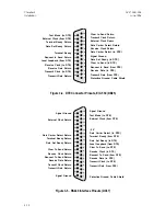
Figure 3-6. V.35 Interface Pinouts (MS34)
Auxiliary Port (T1 DTE)
Access-T provides a port for connection to a PBX, channel bank, or other T1 DTE
that provides D4 or ESF framing. The auxiliary port includes drop-and-insert
capability as described in Chapter 1.
Access-T Series 100, 200, and 400 Units
The
AUX PORT
connector for the Access-T Series 100, 200, and 400 units is a
standard DA15 female connector. Figure 3-7 shows the required wiring to the
AUX PORT
connector.
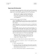
To connect Access-T to the T1 or FT1 DTE, follow these steps:
1. Determine the cable to be used to connect the
AUX
connector and the
T1 DTE.
2.
Install the appropriate cable between the
AUX
connector and the T1
DTE connector on the DTE, making sure that each connector is
oriented properly and mated securely.
Refer to Table 9-A for a complete list of all Larscom cables and part numbers.
A
C
E
D
B
F
L
R
V
Z
d
i
n
k
g
b
X
T
N
J
K
P
U
Y
c
h
m
j
f
a
W
S
M
H
Protective Ground
Signal Ground
Request to Send (from DTE)
Clear to Send (to DTE)
Data Set Ready (to DTE)
Data Carrier Detect (to DTE)
Data Terminal Ready (from DTE)
Ring Indicator (to DTE)
Transmit Data (from DTE)
Receive Data (to DTE)
Transmit Clock (to DTE)
External Clock (from DTE)
Receive Clock (to DTE)
ACST-0351-005
Chapter 3
June 1996
Installation
3-13


