


Power-Up Self-Test
Upon power-up, Access-T performs a self-test. During the self-test, the
STATUS
light on the front panel will turn red. After about seven seconds, when Access-T
has successfully completed the self-test, the light turns green.
If Access-T does not pass the self-test, the
STATUS
LED will remain red. Call
Larscom Customer Service.
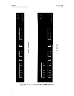
Power Supply Indicators
The power supplies in Access-T 1500 are mounted behind the first panel at the
right of the chassis. If one power supply fails, the other (if installed) will provide
power for the entire unit. Two indicators,
PS1
and
PS2
, indicate the status of the
corresponding power supplies.
There is no power supply indicator on Access-T 100, 200, and 400 units.
Craft Port
Access-T is equipped with a Craft Port. Configured as a DTE, the Craft Port can
be used to connect to the Access-T without having to interrupt operation at the
Supervisory Port. The different Access-T models provide the Craft Port as
follows:
Access-T 100, 200, and 400 Units:
9-pin DE male connector and RS232
DTE interface on the front panel. Figure 3-14 shows the pinouts for the
9-pin D-type Craft Port connector.
Access-T 1500:
25-pin D-type female connector and RS232 DTE interface
on the rear panel. Figure 3-15 shows the pinouts for the 25-pin Craft Port
connector.
The pinouts for this port are illustrated in Chapter 3.
ACST-0351-005
Chapter 4
June 1996
Front-Panel Controls and Indicators
4-5