Product Service 1-800-522-7658
151
5.
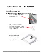
Using the screws, flat washers and locking nuts provided, secure the UV ballast to
the top of the electronics module.
6.
Wire the UV ballast into the wiring harness, following the wiring diagrams located in
Figure 2a-c.
7.
Reattach the electronics module to the top of the cabinet before reconnecting the
electrical power.
8.
Raise the sash, and install the UV lamp by rotating the lamp pins into the sockets.
9.
For all Logic Models:
Lower the sash to fully closed position, plug in the unit, and turn the system
power switch to the "UV" position. The UV lamp will illuminate. Refer to the
user’s manual for further information regarding the proper operation and
maintenance of the UV light.
For All Logic+ models:
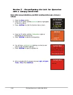
Lower the sash to fully closed position, plug in the unit, and do the following:
12.
Press the
Menu
button.
13.
Press the
▼
button until the
Services
option is highlighted (it will
turn yellow).
14.
Press
OK/Mute
to enter the Services menu screen.
15.
Press the
▼
button until the
Configuration
option is highlighted
(it will turn white).
16.
Press
OK/Mute
to alter the configuration.
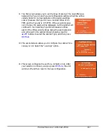
17.
You will see a
warning screen
alerting you that you are about to
alter the BSC’s settings.
18.
Press
OK/Mute
to input the password.
19.
When requested for the password press
Light
,
UV light
,
Timer
,
Timer
then
OK/Mute
.
MAIN MENU
1. MyLogic
TM
2. Settings
3. Service
or
to choose,
OK to select, MENU to escape
or
to choose,
OK to select, MENU to return
Current Settings
Restore Default
Diagnostics
Calibration
Configuration
Service
Configuration
PASSWORD:
ATTENTION!
The following screens are used
to alter the operation of the
Logic. They should only be used
by a qualified certifier as part
of the certification process.
Configuration
OK to proceed, MENU to return


