Page 48
TO CASCADING
UNITS 3 THRU 8
(TYP)
TO CASCADING
UNITS 3 THRU 8
(TYP)
COM2
C
B
A
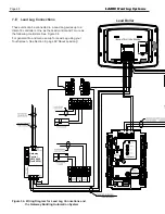
Lead Boiler
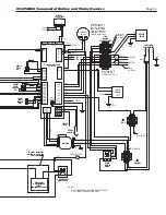
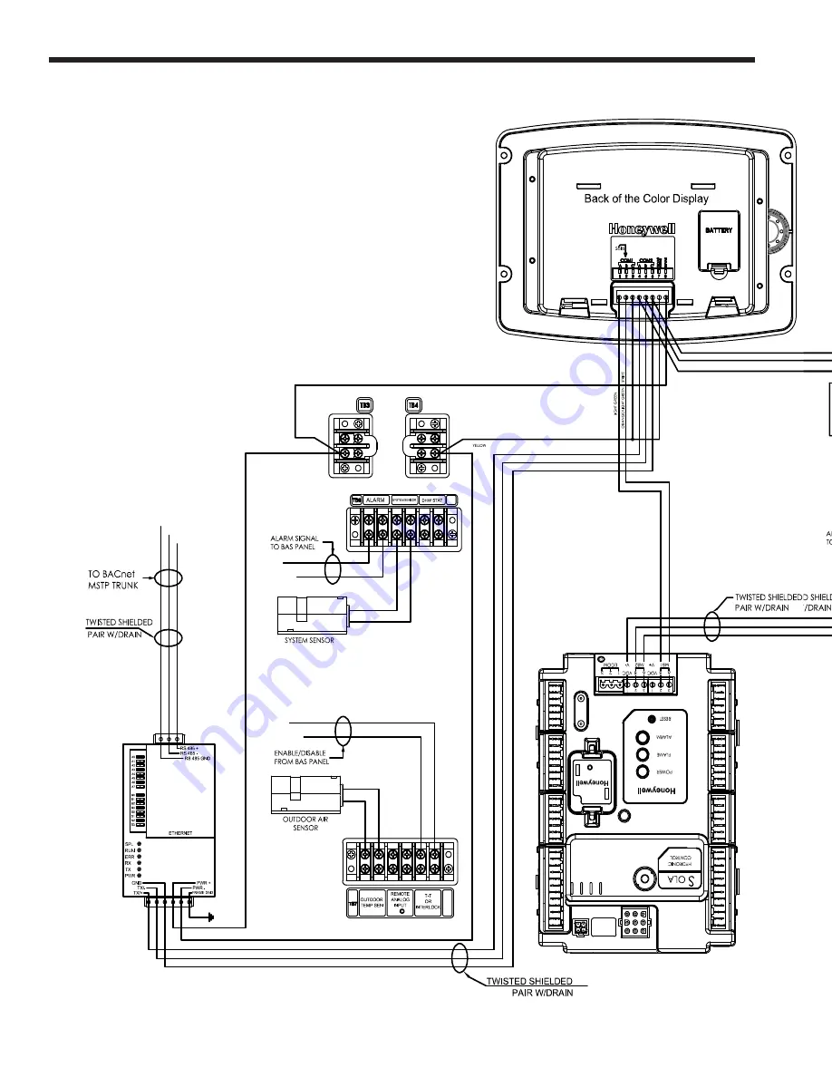
Figure 34. Wiring Diagram for Lead Lag Connections and
the Gateway Building Automation System
TO CASCADING
UNITS 3 THRU 8
(TYP)
TO CASCADING
UNITS 3 THRU 8
(TYP)
COM2
C
B
A
7.E Lead Lag Connections
These units can be connected in a Lead Lag series up to a
total of 8 controllers. One as the Lead control and 7 more as
the following controllers. See Figure 34.
For general info and menu set-up for Lead Lag using your
Touchscreen, See Section 8, page 69 ‘About Lead Lag’.
Gateway
Control
(H2354400
Doc# 4236)
LAARS Heating Systems
Summary of Contents for Neotherm NTH
Page 4: ...LAARS Heating Systems...
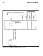
Page 36: ...Page 36 Figure 22 Hydronic Piping Single Boiler Zoning with Circulators LAARS Heating Systems...
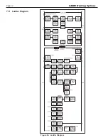
Page 52: ...Page 52 Figure 36 Ladder Diagram 7 H Ladder Diagram LAARS Heating Systems...
Page 100: ...Page 100 Parts Illustration 4 Internal Components Sizes 750 850 LAARS Heating Systems...
Page 102: ...Page 102 Parts Illustration 6 Gas Train Components Sizes 600 850 LAARS Heating Systems...

