Page 92
155
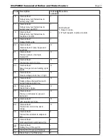
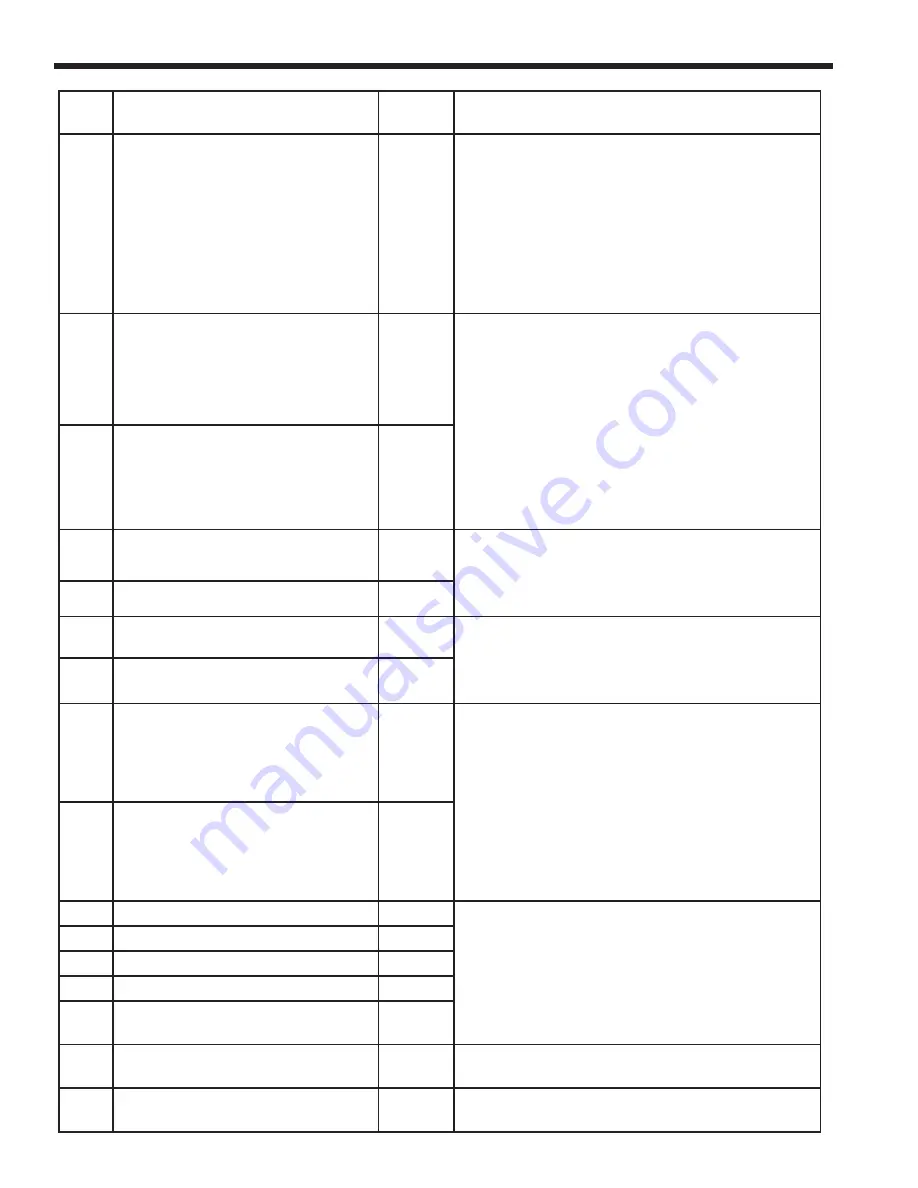
Purge fan switch OFF
H or L
1. Purge fan switch is off when it should be on.
2. Check wiring and correct any errors.
3. Inspect the Purge Fan switch J6 terminal 3
and its connections. Make sure the switch
is working correctly and is not jumpered or
welded.
4. Reset and sequence the relay module.
5. If the fault persists, replace the relay module.
156
Combustion pressure and fl ame
ON
H or L
1. Check that fl ame is not present in the
combustion chamber. Correct any errors.
2. Make sure that the fl ame detector is wired to
the correct terminal.
3. Make sure the F & G wires are protected
from stray noise pickup.
4. Reset and sequence the module, if code
reappears, replace the fl ame detector.
5. Reset and sequence the module, if code
reappears, replace the module.
157
Combustion pressure and fl ame
OFF
L
158
Main valve ON
L
1. Check Main Valve terminal wiring and
correct any errors.
2. Reset and sequence the module. If fault
persists, replace the module.
159
Main valve OFF
L
160
Ignition ON
L
1. Check Ignition terminal wiring and correct
any errors.
2. Reset and sequence the module. If fault
persists, replace the module.
161
Ignition OFF
L
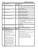
164
Block intake ON
L
1. Check wiring and correct any errors.
2. Inspect the Block Intake Switch to make sure
it is working correctly.
3. Reset and sequence the module.
4. During Standby and Purge, measure the
voltage across the switch. Supply voltage
should be present. If not, the Block Intake
Switch is defective and needs replacing.
5. If the fault persists, replace the relay module.
165
Block intake OFF
L
172
Main relay feedback incorrect
L
Internal Fault.
1. Reset module.
2. If fault repeats, replace module.
174
Safety relay feedback incorrect
L
175
Safety relay open
L
176
Main relay ON at safe start check
L
178
Safety relay ON at safe start
check
L
565
Control looking for outdoor
sensor
H
Ensure Outdoor Sensor is properly connected.
981
Display not communicating with
control
Refer to wire diagram (7G) to ensure display
and control are wired properly.
Code
Description
Lockout
or Hold
Procedure
LAARS Heating Systems
Summary of Contents for Neotherm NTH
Page 4: ...LAARS Heating Systems...
Page 36: ...Page 36 Figure 22 Hydronic Piping Single Boiler Zoning with Circulators LAARS Heating Systems...
Page 52: ...Page 52 Figure 36 Ladder Diagram 7 H Ladder Diagram LAARS Heating Systems...
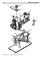
Page 100: ...Page 100 Parts Illustration 4 Internal Components Sizes 750 850 LAARS Heating Systems...
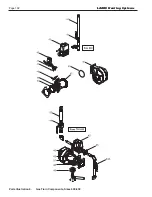
Page 102: ...Page 102 Parts Illustration 6 Gas Train Components Sizes 600 850 LAARS Heating Systems...


