
Page 56
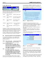
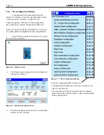
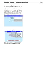
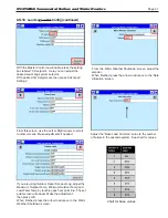
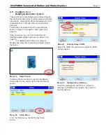
4. The system will present a listing for each group
of parameters that need verification
See Menu 7.
Menu 7.
Safety Parameter Confirmation
5. For each group, check the list carefully. Press
Yes if all of the parameters in the group have
been entered correctly. For each group, you are
given 30 seconds to select Yes/No.
A count-down timer is shown at the bottom of the
screen.
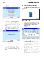
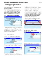
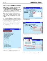
If you made changes in other safety-related
groups, verify the entries in those groups in the
same way. Do this until the following screen
shows
Menu 8. Safety Parameter Reset
6. When the process is complete, the system will
tell you to reset the control system. The Reset
button is located on the front of the controller.
You must press the Reset button within 30
seconds, or the verification will be cancelled. A
count-down timer is shown at the bottom of the
screen.
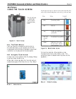
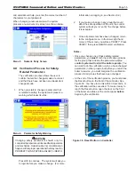
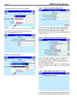
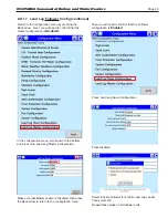
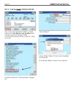
8.E Checking Individual Parameters
1.
From the ‘Home’ screen (Menu 9), press the icon
for the controller.
Menu 9. ‘Home’ screen
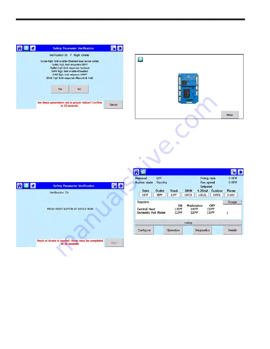
2. The Status Summary page for the controller will
appear. This shows the current operating condition
of the controller, and also shows some of the
configuration settings.
See Menu 10
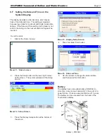
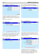
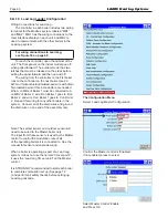
Menu 10. Status Summary Screen
Notice the four buttons at the bottom of each
Status Summary screen:
• Configure – Allows an installer to change some
of the setup parameters used by the system. A
password may be required.
• Operation – Used to adjust the setpoints,
change the fan speed, turn a burner on or off, or
turn the pumps on or off.
• Diagnostics – Allows you to run diagnostic tests,
or check the inputs and outputs used by the
system.
• Details – Allows you to check the status of all of
the setup parameters on the control system.
LAARS Heating Systems
Summary of Contents for Neotherm NTH
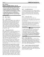
Page 4: ...LAARS Heating Systems...
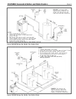
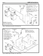
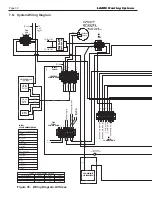
Page 36: ...Page 36 Figure 22 Hydronic Piping Single Boiler Zoning with Circulators LAARS Heating Systems...
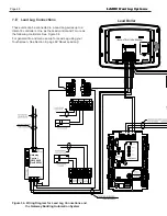
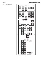
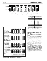
Page 52: ...Page 52 Figure 36 Ladder Diagram 7 H Ladder Diagram LAARS Heating Systems...
Page 100: ...Page 100 Parts Illustration 4 Internal Components Sizes 750 850 LAARS Heating Systems...
Page 102: ...Page 102 Parts Illustration 6 Gas Train Components Sizes 600 850 LAARS Heating Systems...


