Page 17
J
A
G
E
D
B
F
BACK VIEW
C
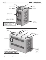
AIR FILTER
WATER
OUTLET
WATER
INLET
BOX
GAS INLET
CONDENSATE
TRAP OUTLET
L
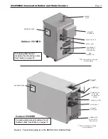
AIR FILTER
KNOCK-OUTS FOR
POWER TO
ALL OPTIONAL
EQUIPMENT
OUTLET
WATER
WATER
INLET
BOX
GAS INLET
CONDENSATE
TRAP OUTLET
D
F
B
J
E
G
A
C
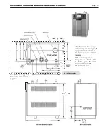
VENT
K
8
21
13
33
26
(66
)
FRONT VIEW
RIGHT SIDE VIEW
BACK VIEW
TOP VIEW
L
AIR FILTER
OUTLET
WATER
WATER
INLET
BOX
GAS INLET
CONDENSATE
TRAP OUTLET
D
F
B
J
E
G
A
C
VENT
K
8
21
13
33
26
(66
)
FRONT VIEW
RIGHT SIDE VIEW
BACK VIEW
TOP VIEW
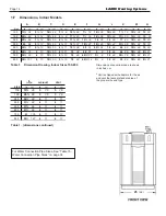
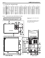
Table 2. (dimensions ontinued)
600 MBH
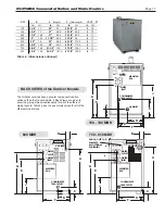
BACK VIEWS of the Outdoor Models
750 - 850 MBH
150 - 199 MBH
SIZE
in
cm
in
cm
in
cm
in
cm
in
cm
in
cm
in
cm
in
cm
in
cm
in
cm
in
cm
in
cm
150
6-1/4"
16
11"
28
13"
33
17-1/4"
43.8
23-1/2"
60
18"
45.7
27"
69
23-1/2"
60
5-1/4"
13
20"
60
25-1/2"
65
3
7.6
199
6-1/4"
16
11"
28
13"
33
17-1/4"
43.8
23-1/2"
60
18"
45.7
27"
69
24-1/2"
60
5-1/4"
13
27"
68.6
32-1/2"
82.5
3
7.6
285
6"
15.5
11"
28
5"
13
17-1/4"
43.8
24"
61
19"
48
28-1/4"
72
12"
30.5
7-1/4"
18.4
27"
68.6
32-1/2"
82.5
4
11
399
8"
15.5
19-1/2"
50
7-3/4"
20
17-1/4"
43.8
24"
61
19"
48
28-1/4"
72
12"
30.5
6"
15.2
31-1/4""
80.5
37-3/4"
96
4
11
500
5"
13
17-3/4"
45
5"
13
8-1/4"
21
24"
61
19"
48
29-1/4"
74
12"
30.5
5.5"
14
38"
96.5
43-1/2"
110.5
4
11
600
33-1/2"
85
3.0"
8
5"
13
8-1/4"
21
24"
61
19"
48
29-1/4"
74
12"
30.5
5-3/4"
14.6
38"
96.5
43-1/2"
110.5
4
11
750
32-3/4"
83.2
3.0"
8
5-1/4"
13.4
17-1/4"
43.8
24"
61
19"
48
29-1/4"
74
12"
30.5
5-3/4"
14.6
51-1/4"
130
57-3/4"
146.7
6
17
850
32-3/4"
83.2
3.0"
8
5-1/4"
13.4
17-1/4"
43.8
24"
61
19"
48
29-1/4"
74
12"
30.5
5-3/4"
14.6
55-3/4"
141.5
61-1/4"
155.5
6
17
E
F
VENT
A
B
C
D
G
J
K
L
(Length)
T
(Total
Length)
Ø
The Outdoor versions have a greater component location
variance than the Indoor models. 4 Back Views are given to
show the piping dimensions/locations for all of the different
piping layouts. Table 2 gives the exact dimensions for all of the
different model sizes.
N
EO
T
HERM
Commercial Boilers and Water Heaters
Summary of Contents for Neotherm NTH
Page 4: ...LAARS Heating Systems...
Page 36: ...Page 36 Figure 22 Hydronic Piping Single Boiler Zoning with Circulators LAARS Heating Systems...
Page 52: ...Page 52 Figure 36 Ladder Diagram 7 H Ladder Diagram LAARS Heating Systems...
Page 100: ...Page 100 Parts Illustration 4 Internal Components Sizes 750 850 LAARS Heating Systems...
Page 102: ...Page 102 Parts Illustration 6 Gas Train Components Sizes 600 850 LAARS Heating Systems...

