background image

3MH

1-4-5

(7)
A paper jam in the 
paper feed section is 
indicated during 
copying (multiple 
sheets in second 
paper feeder).
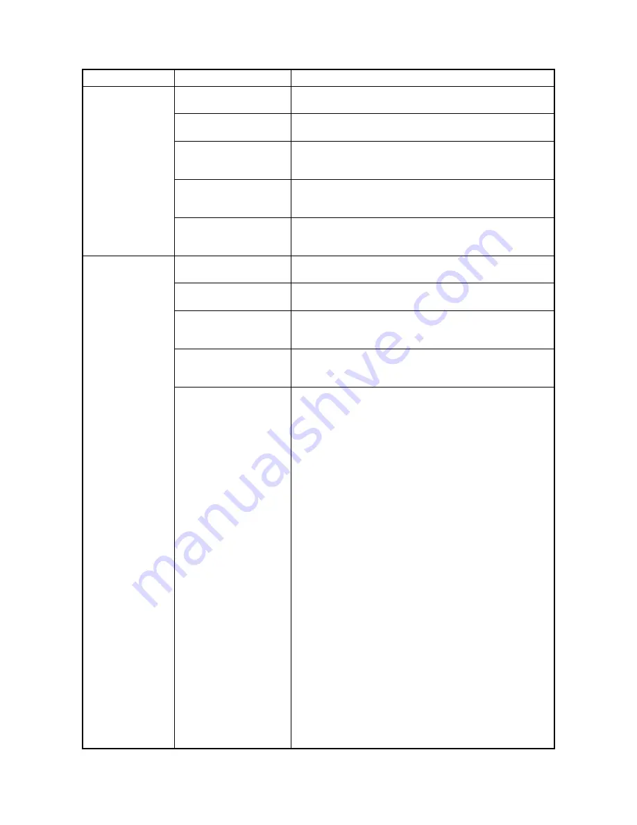
Jam code 23

Deformed guides along the 
paper conveying path.

Check visually and replace.

Broken cassette feed 
switch 1 actuator.

Check visually and replace switch.

Defective cassette feed 
switch 1.

Run maintenance item U031 and turn cassette feed switch 1 on 
and off manually. Replace the switch if indication of the corre-
sponding switch is not light.

Check if the cassette paper 
feed clutch 2 malfunctions.

Run maintenance item U032 and select the cassette paper feed 
clutch 2 to be turned on and off. Check the status and remedy if 
necessary.

Electrical problem with the 
cassette paper feed clutch 
2.

Check (see page 1-4-9).

(8)
A paper jam in the 
paper feed section is 
indicated during 
copying (multiple 
sheets in third paper 
feeder).
Jam code 24

Deformed guides along the 
paper conveying path.

Check visually and replace.

Broken cassette feed 
switch 2 actuator.

Check visually and replace switch.

Defective cassette feed 
switch 2.

Run maintenance item U031 and turn cassette feed switch 2 on 
and off manually. Replace the switch if indication of the corre-
sponding switch is not light.

Check if the cassette paper 
feed clutch 3 malfunctions.

Run maintenance item U032 and select the cassette paper feed 
clutch 3 to be turned on and off. Check the status and remedy if 
necessary.

Electrical problem with the 
cassette paper feed clutch 
3.

Check (see page 1-4-9).

Problem

Causes/check procedures

Corrective measures

Summary of Contents for DF-420

Page 1: ...SERVICE MANUAL Published in May 2009 3MZSM060 First Edition DP 420 PF 420 DF 420 JS 420 FAX System R ...

Page 2: ...icials for details in your area for proper disposal ATTENTION IL Y A UN RISQUE D EXPLOSION SI LA BATTERIE EST REMPLACEE PAR UN MODELE DE TYPE INCORRECT METTRE AU REBUT LES BATTERIES UTILISEES SELON LES INSTRUC TIONS DONNEES Il peut être illégal de jeter les batteries dans des eaux d égout municipales Vérifiez avec les fonc tionnaires municipaux de votre région pour les détails concernant des déche...

Page 3: ...Revision history Revision Date Replaced pages Remarks ...

Page 4: ...This page is intentionally left blank ...

Page 5: ...rsonnel to ensure the safety of their customers their machines as well as themselves during maintenance activities Service personnel are advised to read this booklet carefully to familiarize themselves with the warnings and precautions described here before engaging in maintenance activities ...

Page 6: ... this symbol CAUTION Bodily injury or damage to property may result from insufficient attention to or incorrect compliance with warning messages using this symbol Symbols The triangle symbol indicates a warning including danger and caution The specific point of attention is shown inside the symbol General warning Warning of risk of electric shock Warning of high temperature indicates a prohibited ...

Page 7: ... or dusty place This may cause fire or electric shock Do not install the copier near a radiator heater other heat source or near flammable material This may cause fire Allow sufficient space around the copier to allow the ventilation grills to keep the machine as cool as possible Insufficient ventilation may cause heat buildup and poor copying performance Always handle the machine by the correct l...

Page 8: ... carefully Always check that the copier is correctly connected to an outlet with a ground connection Check that the power cable covering is free of damage Check that the power plug is dust free If it is dirty clean it to remove the risk of fire or electric shock Never attempt to disassemble the optical unit in machines using lasers Leaking laser light may damage eyesight Handle the charger section...

Page 9: ...r trapped wire and missing screws Check that all the caution labels that should be present on the machine according to the instruction handbook are clean and not peeling Replace with new ones if necessary Handle greases and solvents with care by following the instructions below Use only a small amount of solvent at a time being careful not to spill Wipe spills off completely Ventilate the room wel...

Page 10: ...This page is intentionally left blank ...

Page 11: ...First Edition DP 420 ...

Page 12: ...gnosis 1 4 4 1 Self diagnostic function operation panel is a 7 segment type 1 4 4 2 Self diagnostic codes operation panel is a 7 segment type 1 4 4 3 Self diagnostic function operation panel is an LCD type 1 4 4 4 Self diagnostic codes operation panel is an LCD type 1 4 4 1 4 3 Electric problems 1 4 5 1 4 4 Mechanical problems 1 4 6 1 5 Assembly and Disassembly 1 5 1 Precautions for assembly and d...

Page 13: ...3MX 2 4 Appendixes List of maintenance parts 2 4 1 Periodic maintenance procedures 2 4 2 Wiring diagram 2 4 4 ...

Page 14: ...Original type Sheet originals Original size A3 to A5R Ledger to StatementR Original No of sheets 50 sheets or less 50 to 80 g m2 Mixed original sizes 30 sheets or less 50 to 80 g m2 Original scanning speed 53 5 to 107 mm s Power source Electrically connected to the machine Dimensions 559 W x 487 D x 131 H mm 22 W x 19 3 16 D x 5 3 16 H Weight 7 kg 15 4 lbs or less NOTE These specifications are sub...

Page 15: ...3MX 1 1 2 1 1 2 Parts names Figure 1 1 1 1 2 4 6 5 3 2 1 Original table 2 Original width guides 3 Original eject table 4 Document processor top cover 5 Original stopper 6 Cleaning cloth compartment ...

Page 16: ...3MX 1 1 3 1 1 3 Machine cross section Figure 1 1 2 Machine cross section Original path 1 2 3 1 Original feed section 2 Original conveying section 3 Original switchback section ...

Page 17: ...3MX 1 1 4 This page is intentionally left blank ...

Page 18: ...humidity or low temperature and low humidity an abrupt change in the environmental temperature and cool or hot direct air Avoid places subject to dust and vibrations Choose a surface capable of supporting the weight of the machine Place the machine on a level surface maximum allowance inclination 1 Avoid air borne substances that may adversely affect the machine or degrade the photoconductor such ...

Page 19: ...Outer case 3 Inner case 4 Rear upper pad 5 Rear lower pad 6 Front pad 7 Spacer 8 Plastic sheet 9 Plastic bag 10 Cleaning cloth 11 Tray spacer 12 Plastic bag 13 Original mat 14 Plastic bag 15 M4 x 14 screws 16 Pins 17 Angle adjusting plate 18 Plastic bag 19 Installation guide 20 Film 21 Label A 22 Label B 220 V 240 V specifications only ...

Page 20: ...gure 1 2 2 2 Open the document processor top cover 3 Raise the DP feed pulley unit 4 Open the spacer 5 Raise the original table 6 Remove the spacer 7 Remove the plastic bag Figure 1 2 3 Tape Tape Document processor top cover Original table Spacer Plastic bag DP feed pulley unit ...

Page 21: ...3MX 1 2 4 This page is intentionally left blank ...

Page 22: ...ter 10871087 using the numeric keys Enter 001 using the zoom keys or numeric keys and press the start key Enter the maintenance item number using the zoom keys or numeric keys The selected maintenance item is run Press the stop clear key Press the start key Start End Maintenance mode is entered The maintenance item is selected Maintenance mode is exited Repeat the same maintenance item Run another...

Page 23: ... luminosity 1 1 U076 Adjusting the DP automatically U087 Setting DP reading position modification operation ON 35 1 Operation panel and support equipment U203 Checking DP operation U243 Checking the operation of the DP motors U244 Checking the DP switches Image processing U404 Adjusting margins for scanning an original from the DP 2 0 3 0 2 0 2 0 1 Other U905 Checking clearing counts by optional d...

Page 24: ...tory of the main PWB Number of the main ROM Number of the main ROM sub Exp 1 lit Exp 2 lit Exp 3 lit Exp 4 lit Exp 5 lit Exp 1 flashing E Part Code Engine PWB Change history of the engine PWB Number of the engine ROM Number of the engine ROM sub Change history of the engine PWB BOOT Number of the engine PWB BOOT Exp 1 lit Exp 2 lit Exp 3 lit Exp 4 lit Exp 5 lit L Part Code Language Change history ...

Page 25: ...ess the start key 2 Change the setting using the zoom keys Increasing the value moves the image backward and decreasing it moves the image forward Supplement While this maintenance item is being executed copying from an original is available in interrupt copying mode which is activated by pressing the interrupt key Completion Press the stop clear key The screen for selecting a maintenance item No ...

Page 26: ...e the value For copy example 2 decrease the value Figure 1 3 1 6 Press the start key The value is set Caution Check the copy image after the adjustment If the image is still incorrect perform the following adjustments in maintenance mode Completion Press the stop clear key The screen for selecting a maintenance item No is displayed Maintenance item No Description Display Description Setting range ...

Page 27: ...e 2 increase the value of exp 1 Figure 1 3 2 6 Press the start key The value is set Caution Check the copy image after the adjustment If the image is still incorrect perform the following adjustments in maintenance mode Completion Press the stop clear key The screen for selecting a maintenance item No is displayed Maintenance item No Description Exposure indicator Description Setting range Initial...

Page 28: ...e using the zoom keys For copy example 1 increase the value For copy example 2 decrease the value Figure 1 3 3 6 Press the start key The value is set Caution Check the copy image after the adjustment If the image is still incorrect perform the following adjustments in maintenance mode Completion Press the stop clear key The screen for selecting a maintenance item No is displayed Maintenance item N...

Page 29: ... setting using the zoom keys Increasing the setting makes the luminosity higher and decreasing it makes the luminosity lower 3 Press the start key The value is set Supplement While this maintenance item is being executed copying from an original is available in interrupt copying mode which is activated by pressing the interrupt key Completion Press the stop clear key The screen for selecting a mai...

Page 30: ...y Auto adjustment starts When adjustment is complete Gd appears 4 Display each setting value after adjustment using the exposure adjustment keys If a problem occurs during auto adjustment nG is displayed and operation stops Determine the details of the problem and either repeat the procedure from the beginning or adjust the remaining items manu ally by running the corresponding maintenance items C...

Page 31: ...key The setting is set Setting the reference data for identifying dust Available only when the mode is turned on 1 Change the setting using the zoom keys Example The figure indicates the density in 256 levels of gray 0 white 255 black When the setting is 35 data of the level of 35 or higher is regarded as dust and data of lower level is regarded as the background scan data taken when there is no o...

Page 32: ...ional DP on Purpose To check the operation of the DP motors or solenoids Method 1 Press the start key 2 Select the motor or solenoid to be operated using the exposure adjustment keys 3 Press the start key The operation starts 4 To turn each motor off press the stop clear key Completion Press the stop clear key when operation stops The screen for selecting a maintenance item No is displayed Mainten...

Page 33: ... on status of a switch is detected the LEDs on the operation panel corresponding to the operated switch lights Completion Press the stop clear key The screen for selecting a maintenance item No is displayed Maintenance item No Description LEDs Switch Auto Exp Original set switch OSSW Text Photo DP timing switch DPTSW Photo Original detection switch ODSW Text DP original cover switch DPOCSW EcoPrin...

Page 34: ...oom keys Increasing the value makes the margin wider and decreasing it makes the margin narrower Figure 1 3 5 6 Press the start key The value is set Completion Press the stop clear key The screen for selecting a maintenance item No is displayed Maintenance item No Description U403 See the service manual for the machine U402 See the service manual for the machine U404 Exposure indicator Description...

Page 35: ...ting value using the zoom keys The greater the value the larger the amount of slack the smaller the value the smaller the amount of slack If an original non feed jam or oblique feed occurs increase the setting value If wrinkling of original occurs decrease the value 6 Press the start key The value is set Completion Press the stop clear key The screen for selecting a maintenance item No is displaye...

Page 36: ...numeric keys Enter 001 using the cursor up down keys or numeric keys and press the start key Enter the maintenance item number using the cursor up down keys or numeric keys The selected maintenance item is run Press the stop clear key Press the start key Start End Maintenance mode is entered The maintenance item is selected Maintenance mode is exited Repeat the same maintenance item Run another ma...

Page 37: ...g DP automatic adjustment U087 Setting DP reading position modification operation ON 35 1 Operation panel and support equipment U203 Checking DP operation U243 Checking the operation of the DP motors U244 Checking the DP switches Mode setting U326 Setting the black line cleaning indication ON 1 2 Image processing U404 Adjusting margins for scanning an original from the DP 2 0 3 0 2 0 2 0 1 Other U...

Page 38: ... Setting 1 Press the start key 2 Change the setting using the cursor left right keys Increasing the value moves the image backward and decreasing it moves the image forward 3 Press the start key The value is set Supplement While this maintenance item is being executed copying from an original is available in interrupt copying mode which is activated by pressing the interrupt key Completion Press t...

Page 39: ...ease the value For copy example 2 decrease the value Figure 1 3 6 4 Press the start key The value is set Caution Check the copy image after the adjustment If the image is still incorrect perform the following adjustments in maintenance mode Completion Press the stop clear key The screen for selecting a maintenance item No is displayed Maintenance item No Description Display Description Setting ran...

Page 40: ...y 4 Change the setting value using the cursor left right keys For copy example 1 increase the value For copy example 2 decrease the value Figure 1 3 7 5 Press the start key The value is set Caution Check the copy image after the adjustment If the image is still incorrect perform the following adjustments in maintenance mode Maintenance item No Description Display Description Setting range Initial ...

Page 41: ... right keys For copy example 1 increase the value For copy example 2 decrease the value Figure 1 3 8 5 Press the start key The value is set Caution Check the copy image after the adjustment If the image is still incorrect perform the following adjustments in maintenance mode Completion Press the stop clear key The screen for selecting a maintenance item No is displayed Maintenance item No Descript...

Page 42: ...y example 1 increase the value For copy example 2 decrease the value Figure 1 3 9 6 Press the start key The value is set Caution Check the copy image after the adjustment If the image is still incorrect perform the following adjustments in maintenance mode Completion Press the stop clear key The screen for selecting a maintenance item No is displayed Maintenance item No Description Display Descrip...

Page 43: ...value using the cursor left right keys Increasing the setting makes the luminosity higher and decreasing it makes the luminosity lower 3 Press the start key The value is set Supplement While this maintenance item is being executed copying from an original is available in interrupt copying mode which is activated by pressing the interrupt key Completion Press the stop clear key The screen for selec...

Page 44: ...rts When adjustment is complete each adjusted value is displayed If a problem occurs during auto adjustment DATA XX XX is replaced by an error code is displayed and operation stops Should this happen determine the details of the problem and either repeat the pro cedure from the beginning or adjust the remaining items manually by running the corresponding main tenance items Completion Press the sto...

Page 45: ...l is regarded as the background scan data taken when there is no original 2 Press the start key The value is set Completion Press the stop clear key The screen for selecting a maintenance item No is displayed U203 Checking DP operation Description Simulates the original conveying operation separately in the DP Purpose To check the DP operation Method 1 Press the start key 2 Place an original in th...

Page 46: ...Method 1 Press the start key 2 Turn the respective switches on and off manually to check the status When a switch is detected to be in the ON position the display for that switch will be highlighted Completion Press the stop clear key The screen for selecting a maintenance item No is displayed Maintenance item No Description Display Motors and solenoids F MOT Original feed motor OFM is turned on C...

Page 47: ...lack line decrease by the rubbish on the platen when scanning from the DP Setting 1 Press the start key 2 Select ON or OFF using the cursor up down keys Initial setting ON 3 Press the start key The setting is set Completion Press the stop clear key The screen for selecting a maintenance item No is displayed Maintenance item No Description Display Description ON Displays the cleaning guidance OFF N...

Page 48: ...r left right keys Increasing the value makes the margin wider and decreasing it makes the margin narrower Figure 1 3 11 6 Press the start key The value is set Completion Press the stop clear key The screen for selecting a maintenance item No is displayed Maintenance item No Description U403 See the service manual for the machine U402 See the service manual for the machine U404 Display Description ...

Page 49: ...ey to make a test copy 5 Change the setting value using the cursor left right keys The greater the value the larger the deflection the smaller the value the smaller the deflection If an original non feed jam or oblique feed occurs increase the setting value If wrinkling of original occurs decrease the value 6 Press the start key The value is set Completion Press the stop clear key The screen for s...

Page 50: ...achine immediately stops operation and a message is shown on the machine operation panel To remove the jammed original open the document processor top cover To reset the original misfeed detection open and close the document processor top cover 2 Original misfeed detection conditions Figure 1 4 1 OSBSW OSBSW OSBSW DPTSW ...

Page 51: ... orig inal conveying section 2 During original conveying in the duplex mode DP timing switch DPTSW does not turn off within specified time of the original conveying motor OCM turning on 9900 pulses 74 An original jam in the orig inal conveying section 3 During secondary original feed in the duplex mode DP tim ing switch DPTSW does not turn on within specified time of the original switchback motor ...

Page 52: ...ing motor malfunctions Run maintenance item U243 and select the original conveying motor to be turned on and off Check the status and remedy if nec essary 4 An original jams in DP is indicated dur ing copying an origi nal jam in the original conveying section 2 Jam code 73 Defective DP timing switch Run maintenance item U244 and turn the DP timing switch on and off manually Replace the switch if i...

Page 53: ... error occurs frequently a fault may have occurred Check the details of the C call to take proper measures Table 1 4 1 4 Self diagnostic codes operation panel is an LCD type Code Contents Remarks Causes Check procedures corrective measures A0410 Document processor communication problem Communication fails five times succes sively Document proces sor installed incor rectly Check the installation st...

Page 54: ...l If none replace the motor 3 The switchback feed shift solenoid or switchback pressure solenoid does not operate 1 Defective solenoid coil Check for continuity across the coil If none replace the solenoid 2 Poor contact in the con nector terminals Reinsert the connector Also check for continuity within the con nector cable If none remedy or replace the cable 3 Defective DP main PWB Run maintenanc...

Page 55: ... 1 5 2 Electrical problem with the original feed motor See page 1 4 5 2 Originals jam Originals outside the specifications are used Use only originals conforming to the specifi cations The surfaces of the DP forwarding pulley DP original feed pulley or DP separation pad are dirty with paper powder Check and clean them with isopropyl alcohol if they are dirty Check if the contact between the eject ...

Page 56: ...to the equipped hard disk When handling PWBs printed wiring boards do not touch parts with bare hands The PWBs are susceptible to static charge Do not touch any PWB containing ICs with bare hands or any object prone to static charge When removing the hook of the connector be sure to release the hook Take care not to get the cables caught To reassemble the parts use the original screws If the types...

Page 57: ... DP feed pulley Procedure Removing the DP forwarding pulley 1 Open the document processor top cover 2 Raise the DP feed pulley unit Release the claw holding the DP forwarding pulley shaft and then pull out the shaft 3 Remove the DP forwarding pulley Figure 1 5 1 DP forwarding pulley Document processor top cover DP feed pulley unit DP feed pulley unit Claw DP forwarding pulley shaft ...

Page 58: ...f the original feed guide into the groove of the DP feed pulley shaft Align the original feed guide with the side affixed with a C label facing the front side of the machine 5 Remove the DP feed pulley unit from the DP Figure 1 5 2 DP feed pulley shaft Stop ring Original feed guide Original feed guide Original feed guide Groove DP feed pulley unit DP feed pulley shaft Label C ...

Page 59: ...e DP feed pulley unit 7 Remove DP feed pulley from the DP feed pulley shaft 8 Clean or replace the DP forwarding pulley and the DP feed pulley Refit all the removed parts Figure 1 5 3 Stop ring Stop ring DP feed pulley unit DP feed pulley shaft DP feed pulley shaft DP feed pulley ...

Page 60: ...DP separation pad Procedure 1 Remove the DP feed pulley unit see page 1 5 2 2 Push the inserted parts of the DP separation pad and then remove the DP separation pad 3 Clean or replace the DP separation pad Refit all the removed parts Figure 1 5 4 DP separation pad DP separation pad Inserted part Inserted part ...

Page 61: ...eeds the refer ence value perform the following adjust ment Reference value For simplex copying Within 3 0 mm For duplex copying Within 4 0 mm Figure 1 5 5 3 Open the DP and loosen two adjusting screws of right hinge 4 Adjust the position of the DP For copy example 1 Move the DP down For copy example 2 Move the DP up Amount of change per scale Approx 0 5 mm 5 Tighten two adjusting screws Figure 1 ...

Page 62: ... Align original mat corner that has 90 degrees of angle with the inner left corner of the original instruction panel 8 Close the DP slowly to attach the original mat 9 Make a test copy again 10 Repeat steps 3 to 9 above until the gap of the leading edge falls within the reference values Figure 1 5 7 Original mat ...

Page 63: ...s the refer ence value perform the following adjust ment Reference value For simplex copying Within 3 0 mm For duplex copying Within 4 0 mm Figure 1 5 8 3 Open the DP and release two latches using a flat head screwdriver Figure 1 5 9 4 Release three latches using a flat head screwdriver and remove the document pro cessor rear cover Figure 1 5 10 3 mm 4 mm 3 mm 4 mm Original Copy example 1 Copy exa...

Page 64: ...ace the original mat with its hook and loop fasteners up over the platen Align original mat corner that has 90 degrees of angle with the inner left corner of the original instruction panel 9 Close the DP slowly to attach the original mat 10 Make a test copy again 11 Repeat steps 3 to 10 above until the gap of the trailing edge falls within the reference values Figure 1 5 13 3 mm 4 mm 3 mm 4 mm Ori...

Page 65: ...3MX 1 5 10 This page is intentionally left blank ...

Page 66: ...riginal mode Figure 2 1 1 Original feed section 1 1 20 20 21 21 2 3 4 5 18 18 19 19 8 14 14 15 15 9 10 10 11 11 13 13 12 12 7 6 17 17 16 16 23 23 22 22 24 24 1 20 21 2 3 4 5 18 19 8 14 15 9 10 11 13 12 7 6 17 16 23 22 24 1 DP forwarding pulleys 2 DP feed pulley 3 DP separation pad 4 Conveying pulley 5 Conveying roller 6 Conveying pulley 7 Conveying pulley 8 Switchback feedshift guide 9 Switchback ...

Page 67: ... 2 1 2 Figure 2 1 2 DPMPWB YC4 7 9 10 12 YC7 2 3 YC3 1 3 4 6 YC6 2 YC10 2 YC7 5 YC9 2 OSBM OFM OCM OSSW OSBSW DPTSW SBFSSOL SBPSOL B A _B _A B A _B _A YC4 1 3 4 6 B A _B _A TMG SW SET SW REV SW ACT ACT RET ...

Page 68: ...ing original jams in the original switchback section Figure 2 1 3 First side scanning Switchback tray Original conveying motor OCM Forwerd rotation Original switchback motor OSBM Forwerd rotation Switchback feedshift solenoid SBFSSOL ON Original switchback operate Original conveying motor OCM Stop Original switchback motor OSBM Reverse rotation Switchback feedshift solenoid SBFSSOL OFF Second side...

Page 69: ...3MX 2 1 4 This page is intentionally left blank ...

Page 70: ...3MX 2 2 1 2 2 Electrical Parts Layout 2 2 1 Electrical parts layout 1 PWBs Figure 2 2 1 PWBs 1 DP main PWB DPMPWB Controls electrical components of the DP 1 Machine front Machine inside Machine rear ...

Page 71: ...resence of an original 3 DP timing switch DPTSW Detects the original scanning timing 4 Original switchback switch OSBSW Detects an original misfeed in the original switchback section 5 Original size width switch OSWSW Detects the width of the original 6 Original size length switch OSLSW Detects the length of the original 7 DP open close switch OPOCSW Detects the opening closing of the DP 1 2 4 5 6...

Page 72: ...s the original feed section 2 Original conveying motor OCM Drives the original conveying section 3 Original switchback motor OSBM Drives the original switchback section 4 DP cooling fan motor DPCFM Cools the drive section 1 3 2 4 Machine front Machine inside Machine rear ...

Page 73: ...ds Figure 2 2 4 Solenoids 1 Switchback feedshift solenoid SBFSSOL Operates the switchback feedshift guide 2 Switchback pressure solenoid SBPSOL Operates the switchback pulley 2 1 Machine front Machine inside Machine rear ...

Page 74: ...igure 2 3 1 DP main PWB block diagram DPMPWB DPILSW 24 V 5 V ORGVSYNC SCLK SDO SDI RDY SEL R24 V Cover open detection SBFSSOL SBPSOL Motor driver Motor driver Motor driver OFM OCM OSBM DPTSW OSSW OSWSW OSLSW CPU EEPROM Buffer Machine DPOCSW OSBSW DPCFM EPWB ...

Page 75: ...3MX 2 3 2 Figure 2 3 2 DP main PWB silk screen diagram YC11 YC10 YC6 YC9 YC4 YC3 YC5 1 1 1 1 1 6 2 10 4 4 5 YC7 YC8 U4 YC1 YC2 5 12 1 1 6 5 1 1 1 1 8 3 3 YC12 7 1 ...

Page 76: ... 24 V DC 24 V DC supply 6 _A O 0 24 V DC pulse OFM drive control signal _A YC4 1 B O 0 24 V DC pulse OCM drive control signal B Connected to the origi nal convey ing motor and original switchback motor 2 COM_A R24V O 24 V DC 24 V DC supply 3 A O 0 24 V DC pulse OCM drive control signal A 4 _B O 0 24 V DC pulse OCM drive control signal _B 5 COM_B R24V O 24 V DC 24 V DC supply 6 _A O 0 24 V DC pulse...

Page 77: ...tch original size length switch and original size width switch 2 REV SW I 0 5 V DC OSBSW On Off 3 GND Ground 4 SZ_SW_L I 0 5 V DC OSLSW On Off 5 5V O 5 V DC 5 V DC supply 6 GND Ground 7 SZ_SW_W I Analog OSWSW detection voltage 8 5V O 5 V DC 5 V DC supply YC10 1 GND Ground Connected to original set switch 2 SET SW I 0 5 V DC OSSW On Off 3 5V O 5 V DC 5 V DC supply YC11 1 5V O 5 V DC 5 V DC supply C...

Page 78: ...CASSETTE 2A107060 3 46 Conveying roller PARTS CONVEYING ROLLER ASSY SP 303K594010 3K594010 4 9 Conveying pulley PULLEY CONVEYING 3HL08080 3 61 Conveying pulley PULLEY CONVEYING 3HL08080 4 37 Conveying pulley PULLEY LOOP 3HL10140 4 46 Scanning guide GUIDE READING 303K524010 3K524010 2 17 Switchback roller PARTS ROLLER LOOP SP 303K594050 3K594050 4 19 Switchback pulley PULLEY LOOP 3HL10140 4 46 Ejec...

Page 79: ...aintenance cycle Points and cautions Page Original con veying sec tion Conveying roller Clean Every service Clean with alcohol or a dry cloth Conveying pulley Check or clean 150K Clean with alcohol or a dry cloth if it is dirty Scanning guide Clean Every service Clean with alcohol or a dry cloth Section Maintenance part location Method Maintenance cycle Points and cautions Page Original switchback...

Page 80: ...ction Maintenance part location Method Maintenance cycle Points and cautions Page Covers Covers Clean Every service Clean with alcohol Slit glass Check or clean Every service Clean with a dry cloth do not clean with a wet cloth or alco hol ...

Page 81: ...5 6 7 8 9 10 11 12 13 14 15 16 1 2 3 4 5 6 7 8 9 10 11 12 13 14 15 16 1 2 3 4 5 6 7 8 9 10 1 2 3 4 5 6 7 8 9 10 COM N O N C Engine I F power source Engine I F signal DPMPWB Shield 1 1 2 2 3 3 4 4 24V N C R24V N C COV_OPN 5V TMG SW GND 5V N C N C N C GND 1 2 3 4 5 1 2 3 1 2 3 4 5 1 2 3 4 5 6 7 1 2 3 1 2 2 1 1 2 3 2 1 5V 1 2 SZ_SW_W OSWSW OSWSW 1 6 1 2 5 2 3 4 3 4 3 4 5 2 5 6 1 6 1 2 3 4 5 6 7 8 9 1...

Page 82: ...First Edition PF 420 ...

Page 83: ...gment type 1 4 6 2 Self diagnostic codes operation panel is a 7 segment type 1 4 6 3 Self diagnostic function operation panel is an LCD type 1 4 7 4 Self diagnostic codes operation panel is an LCD type 1 4 7 1 4 3 Image formation problems 1 4 8 1 The leading edge of the image is consistently misaligned with the original 1 4 8 2 The leading edge of the image is sporadically misaligned with the orig...

Page 84: ...3MH 2 4 Appendixes List of maintenance parts 2 4 1 Periodic maintenance procedures 2 4 1 Wiring diagram 2 4 2 ...

Page 85: ...d recycled Paper size A3 B4 A4 A4R B5 B5R A5R Folio Ledger Legal OficioII Letter LetterR StatementR 8K 16K Paper capacity 300 sheets 80 g m2 Power source Electrically connected to the machine Dimensions 568 W x 546 D x 135 H mm 22 3 8 W x 21 1 2 D x 5 5 16 H Weight 6 kg 13 2 lbs NOTE These specifications are subject to change without notice ...

Page 86: ...3MH 1 1 2 1 1 2 Parts names Figure 1 1 1 2 1 3 3 4 1 Cassette 2 Cassette left cover 3 Paper width guides 4 Paper length guide ...

Page 87: ...3MH 1 1 3 1 1 3 Machine cross section Figure 1 1 2 Machine cross section Paper path ...

Page 88: ...3MH 1 1 4 This page is intentionally left blank ...

Page 89: ...humidity or low temperature and low humidity an abrupt change in the environmental temperature and cool or hot direct air Avoid places subject to dust and vibrations Choose a surface capable of supporting the weight of the machine Place the machine on a level surface maximum allowance inclination 1 Avoid air borne substances that may adversely affect the machine or degrade the photoconductor such ...

Page 90: ...n Guide for installation 1 Paper feeder 2 Outer case 3 Bottom left pad 4 Bottom right pad 5 Top left pad 6 Top right pad 7 Plastic sheet 8 Plastic bag 9 Plastic bag 10 Cover labels 11 Plastic bag 12 Screw M3 x 8 13 Screw M3 x 12 14 Connector cover 15 Cursor pins 16 Cassette size label 17 Installation guide 18 Bar code labels ...

Page 91: ... 1 2 3 2 Remove the tapes and spacer Procedure 1 Remove two tapes 2 Remove the spacer Figure 1 2 2 3 Pull the cassette out and remove the tape 4 Push the cassette back in Figure 1 2 3 Tape Spacer Tape Tape ...

Page 92: ...t screw P N 7BB202308H Procedure 1 Remove the screw and the pin and then remove the cassette rear cover 2 Pull out the cassette Figure 1 2 4 3 Pass the cassette heater cable through the hole at the machine rear side 4 Insert the stay of the cassette heater into the hole at the machine rear side 5 Attach the cassette heater using the M3 x 8 P tight screw Figure 1 2 5 Screw Pin Cassette rear cover C...

Page 93: ...3MH 1 2 5 6 Connect the connector of the cassette heater cable to the connector of the machine 7 Refit all the removed parts Figure 1 2 6 Cassette heater cable Connector ...

Page 94: ...3MH 1 2 6 This page is intentionally left blank ...

Page 95: ...ter 10871087 using the numeric keys Enter 001 using the zoom keys or numeric keys and press the start key Enter the maintenance item number using the zoom keys or numeric keys The selected maintenance item is run Press the stop clear key Press the start key Start End Maintenance mode is entered The maintenance item is selected Maintenance mode is exited Repeat the same maintenance item Run another...

Page 96: ...center line Adjusting the trailing edge margin Adjusting the leading edge registration 2 8 0 0 0 0 0 0 0 0 0 8 1 2 4 0 0 0 0 0 0 0 0 0 0 1 2 0 1 2 0 2 0 2 0 2 0 2 0 2 0 1 U051 Adjusting the deflection in the paper 30 20 0 20 20 20 1 U053 Performing fine adjustment of the motor speed 0 3 0 7 0 5 0 0 0 0 5 1 0 1 0 1 0 3 1 Mode setting U341 Specific paper feed location setting for printing function O...

Page 97: ...hange history of the main PWB Number of the main ROM Number of the main ROM sub Exp 1 lit Exp 2 lit Exp 3 lit Exp 4 lit Exp 5 lit Exp 1 flashing E Part Code Engine PWB Change history of the engine PWB Number of the engine ROM Number of the engine ROM sub Change history of the engine PWB BOOT Number of the engine PWB BOOT Exp 1 lit Exp 2 lit Exp 3 lit Exp 4 lit Exp 5 lit L Part Code Language Change...

Page 98: ... each switch on and off manually to check the status When the on status of a switch is detected the original size indicator corresponding to the operated switch lights Completion Press the stop clear key The screen for selecting a maintenance item No is displayed Maintenance item No Description Display Motor A Drive motor DM is turned ON 2F Drum motor DRM is turned ON F1 Cassette drive motor 1 CDM...

Page 99: ...e adjustment keys 3 Press the start key The selected clutch turns on for 1 s Completion Press the stop clear key The screen for selecting a maintenance item No is displayed Maintenance item No Description Display Clutch P1 Paper feed clutch PFCL Pb MP solenoid MPSOL A1 Registration clutch RCL d1 Duplex feed clutch DUPFCL P2 Cassette paper feed clutch 1 CPFCL1 P3 Cassette paper feed clutch 2 CPFCL2...

Page 100: ...ess the start key to output a test pattern 5 Change the setting value using the zoom keys For output example 1 decrease the value For output example 2 increase the value Figure 1 3 1 Maintenance item No Description Image mode LEDs group No Description 1 Leading edge registration adjustment 2 Center line adjustment 3 Trailing edge margin adjustment 4 Leading edge registration adjustment for printer...

Page 101: ...If the image is still incorrect perform the following adjustments in maintenance mode Maintenance item No Description U071 See the service manual for the machine U066 See the service manual for the machine U034 Exposure indicator Description Setting range Initial setting Change in value per step Exp 1 lit Paper feed from cassette 7 0 to 10 0 2 4 0 1 mm Exp 2 lit Paper feed from MP tray 7 0 to 10 0...

Page 102: ...Figure 1 3 4 6 Press the start key The value is set Completion Press the stop clear key The screen for selecting a maintenance item No is displayed Maintenance item No Description Description Setting range Initial setting Change in value per step Trailing edge margin adjustment 4 0 to 10 0 2 0 0 1 mm Correct image Output example Trailing edge margin Exposure indicator Description Setting range Ini...

Page 103: ...alue the larger the amount of slack the smaller the value the smaller the amount of slack Figure 1 3 5 6 Press the start key The value is set Completion Press the stop clear key The screen for selecting a maintenance item No is displayed Maintenance item No Description Exposure indicator Description Setting range Initial setting Change in value per step Exp 1 lit Paper feed from cassette 50 to 127...

Page 104: ...makes the image shorter in the main scanning direction and decreasing it makes the image longer in the main scanning direction 4 Press the start key The value is set Completion Press the stop clear key The screen for selecting a maintenance item No is displayed Maintenance item No Description Image mode LEDs Exposure indicator Description Setting range Initial setting Exp 1 lit Exp 2 lit Exp 3 lit...

Page 105: ...not be used for copy output Setting 1 Press the start key 2 Select the paper feed location for the printer using the exposure adjustment keys 3 Select on or oFF using the zoom keys 4 Press the start key The setting is set Completion Press the stop clear key The screen for selecting a maintenance item No is displayed Maintenance item No Description Display Description Exp 1 Cassette Exp 2 First pap...

Page 106: ...s cleared Completion Press the stop clear key The screen for selecting a maintenance item No is displayed Maintenance item No Description Image mode LED group No Exposure indicator Copy quantity display count value 1 Exp 1 Exp 2 Exp 3 First 3 digits of MP copy count Last 3 digits of MP copy count Clearing the count CLE 2 Exp 1 Exp 2 Exp 3 First 3 digits of the cassette copy count Last 3 digits of ...

Page 107: ...numeric keys Enter 001 using the cursor up down keys or numeric keys and press the start key Enter the maintenance item number using the cursor up down keys or numeric keys The selected maintenance item is run Press the stop clear key Press the start key Start End Maintenance mode is entered The maintenance item is selected Maintenance mode is exited Repeat the same maintenance item Run another ma...

Page 108: ... edge registration Adjusting the center line Adjusting the trailing edge registration 2 8 0 0 0 0 0 0 0 0 0 8 1 2 4 0 0 0 0 0 0 0 0 0 0 1 2 0 1 U051 Adjusting the deflection in the paper 30 20 0 20 20 20 1 U053 Setting the adjustment of the motor speed 0 3 0 7 0 5 0 0 0 1 0 1 0 3 0 0 0 0 0 5 0 0 1 Mode setting U341 Specific paper feed location setting for printing function Other U901 Checking copy...

Page 109: ...s 3 Press the start key The operation starts 4 To stop operation press the stop clear key Completion Press the stop clear key after operation stops The screen for selecting a maintenance item No is displayed Display Description MAIN Main ROM ENGINE Engine ROM LANG St Standard language ROM LANG Op Optional language ROM MAIN BOOT Boot of main ROM PRINTER Printer ROM NWS Optional network scanner ROM ...

Page 110: ...lutch or solenoid Method 1 Press the start key 2 Select the clutch or solenoid to be operated using the cursor up down keys 3 Press the start key The clutch or solenoid turns on for 1 s Completion Press the stop clear key The screen for selecting a maintenance item No is displayed Maintenance item No Description Display Switches EJE Eject switch ESW RES Registration switch RSW PF2 Cassette feed sw...

Page 111: ...ecrease the value For output example 2 increase the value Figure 1 3 7 5 Press the start key The value is set Caution Check the copy image after the adjustment If the image is still incorrect perform the following adjustments in maintenance mode Maintenance item No Description Display Description ADJ RCL ON TIMING Leading edge registration adjustment ADJ LSU ON TIMING Center line adjustment ADJ MG...

Page 112: ...owing adjustments in maintenance mode Maintenance item No Description Display Description Setting range Initial setting Change in value per step LSU OUT Paper feed from cassette 7 0 to 10 0 2 4 0 1 mm LSU BYP Paper feed from MP tray 7 0 to 10 0 0 0 0 1 mm LSU T1 Paper feed from first paper feeder 7 0 to 10 0 0 0 0 1 mm LSU T2 Paper feed from second paper feeder 7 0 to 10 0 0 0 0 1 mm LSU T3 Paper ...

Page 113: ...ys For output example increase the value Figure 1 3 9 5 Press the start key The value is set Completion Press the stop clear key The screen for selecting a maintenance item No is displayed Maintenance item No Description Display Description Setting range Initial setting Change in value per step MGN REAR Trailing edge margin adjustment 4 0 to 10 0 2 0 0 1 ms Correct image Output example Trailing ed...

Page 114: ...se the value For output example 2 decrease the value The greater the value the larger the deflection the smaller the value the smaller the deflection Figure 1 3 10 6 Press the start key The value is set Completion Press the stop clear key The screen for selecting a maintenance item No is displayed Maintenance item No Description Display Description Setting range Initial setting PF1 Paper feed from...

Page 115: ...set Completion Press the stop clear key The screen for selecting a maintenance item No is displayed Maintenance item No Description Display Description Setting range Initial setting MAIN Drive motor speed adjustment 5 0 to 5 0 0 3 POLY Polygon motor speed adjustment 5 0 to 5 0 0 7 EJE Eject motor speed adjustment 5 0 to 5 0 0 5 DRUM Drum motor speed adjustment 5 0 to 5 0 0 0 BYP Motor speed adjust...

Page 116: ...eed locations Purpose To check the time to replace consumable parts Also to clear the counts after replacing the consumable parts Method 1 Press the start key The counts by paper feed locations are displayed 2 Change the screen using the cursor left right keys When an optional paper feed device is not installed the corresponding count is not displayed Clearing 1 Select the count to be cleared usin...

Page 117: ...sfeed occurs the machine immediately stops copying and displays the jam location on the operation panel Paper misfeed detection can be reset by opening and closing the cassette left cover to turn safety switch off and on 2 Paper misfeed detection conditions Figure 1 4 1 CFSW1 CFSW2 CPFCL1 CPFCL2 CPFCL3 ...

Page 118: ...on 1916 ms Cassette feed switch 1 CFSW1 does not turn off within specified time of cassette feed switch 2 CFSW2 turning off 1916 ms Left cover is opened in prior to the cassette feed switch 1 CFSW1 is turned off 16 Misfeed in vertical paper conveying sec tion 2 Cassette feed switch 1 CFSW1 does not turn on within specified time of cassette feed switch 2 CFSW2 turning on 1916 ms Left cover is opene...

Page 119: ...ny deformed pulley Broken cassette feed switch 1 actuator Check visually and replace switch Defective cassette feed switch 1 Run maintenance item U031 and turn cassette feed switch 1 on and off manually Replace the switch if indication of the corre sponding switch is not light Check if the cassette paper feed clutch 2 malfunctions Run maintenance item U032 and select the cassette paper feed clutch...

Page 120: ...tch if indication of the corresponding switch is not light Cassette feed switch 1 2 Check if the paper feed clutch cassette paper feed clutch 1 or 2 malfunctions Run maintenance item U032 and select the clutch to be turned on and off Check the status and remedy if necessary Electrical problem with the paper feed clutch cassette paper feed clutch 1 or 2 Check see page 1 4 9 Defective feed pulleys o...

Page 121: ...ry Electrical problem with the cassette paper feed clutch 2 Check see page 1 4 9 8 A paper jam in the paper feed section is indicated during copying multiple sheets in third paper feeder Jam code 24 Deformed guides along the paper conveying path Check visually and replace Broken cassette feed switch 2 actuator Check visually and replace switch Defective cassette feed switch 2 Run maintenance item ...

Page 122: ...r installed incor rectly Check the installation state of the first paper feeder and adjust it if it is not properly installed Defective PWB Replace the main engine PWB or cassette main PWB and check for correct operation A0500 Second paper feeder communication problem Communication fails five times succes sively Second paper feeder installed incorrectly Check the installation state of the second p...

Page 123: ... Check procedures corrective measures C0420 First paper feeder communication problem Communication fails five times succes sively First paper feeder installed incor rectly Check the installation state of the first paper feeder and adjust it if it is not properly installed Defective PWB Replace the engine PWB or cassette main PWB and check for correct operation C0500 Second paper feeder communicati...

Page 124: ...034 to readjust the leading edge registration see page 1 3 6 17 Copy example Causes Check procedures corrective measures Paper feed clutch MP solenoid or registration clutch installed or operat ing incorrectly Check the installation position and operation of each clutch or solenoid If any of them operates incorrectly replace it Copy example Causes Check procedures corrective measures Misadjusted i...

Page 125: ...tte main PWB Run maintenance item U032 and check if following terminals on the cassette main PWB goes low If not replace the cassette main PWB Cassette paper feed clutch YC8 2 on the cassette main PWB 4 The message requesting paper to be loaded is shown when paper is present on the cas sette 1 Poor contact in the con nector terminals of cas sette paper switch Reinsert the connector Also check for ...

Page 126: ...rt the connector Also check for continuity within the con nector cable If none remedy or replace the cable 2 Defective cassette left cover safety switch Check for continuity across each switch If there is no continuity when the switch is on replace it 8 Others 1 Wiring is broken shorted or makes poor contact Check for continuity If none repair Problem Causes Check procedures corrective measures ...

Page 127: ...e 1 4 9 2 Skewed paper feed Width guide in a cassette installed incorrectly Check the width guide visually and correct or replace if necessary Deformed width guide in a cassette Check visually and replace any deformed guide 3 Multiple sheets of paper are fed at one time Paper is extremely curled Change the paper Check if the cassette separation pulley is worn Replace the cassette separation pulley...

Page 128: ...3MH 1 4 12 This page is intentionally left blank ...

Page 129: ... power switch before pressing the power key to off may cause damage to the equipped hard disk When handling PWBs printed wiring boards do not touch parts with bare hands The PWBs are susceptible to static charge Do not touch any PWB containing ICs with bare hands or any object prone to static charge When removing the hook of the connector be sure to release the hook Take care not to get the cables...

Page 130: ...r side of the feed roller and slide the bush toward the inside 3 Lift the rear of the feed roller upward Slide the feed roller toward the rear side and remove the roller from the paper feeder Figure 1 5 1 4 Remove the gear spring pin and two bushes from the feed roller 5 Replace the feed roller and refit all the removed parts Figure 1 5 2 Feed roller Stop ring Bush Feed roller Bush Gear Spring pin...

Page 131: ...y Procedure 1 Pull out the cassette 2 Remove the screw and remove the lower paper feed unit Figure 1 5 3 3 Release two hooks and remove the separa tion pulley unit from the lower paper feed unit Figure 1 5 4 Lower paper feed unit Screw Hook Hook Separation pulley unit Separation pulley unit Separation pulley unit Lower paper feed unit ...

Page 132: ...aft from the separation pulley unit 5 Remove the cassette separation pulley from the separation pulley shaft 6 Replace the cassette separation pulley and refit all the removed parts Figure 1 5 5 Cassette separation pulley Separation pulley shaft ...

Page 133: ...move the feed roller see 1 5 2 2 Remove the lower paper feed unit see 1 5 3 3 Remove the screw and the pin and then remove the cassette rear cover Figure 1 5 6 4 Remove the connector of the cassette paper feed clutch 5 Remove the stop ring and remove the cas sette paper feed clutch 6 Remove the stop ring and the bush Figure 1 5 7 Screw Pin Cassette rear cover Cassette paper feed clutch Stop ring S...

Page 134: ... upper paper feed unit Figure 1 5 8 8 Remove the springs stop ring and bush and then remove the shaft holder from the upper paper feed unit Figure 1 5 9 Screw Upper paper feed unit Upper paper feed unit Stop ring Bush Spring Spring Shaft holder ...

Page 135: ...rom the upper paper feed unit 11 Remove the collar and the cassette paper feed pulley from the upper paper feed shaft 12 Replace the cassette forwarding pulley and cassette paper feed pulley and refit all the removed parts Figure 1 5 10 Cassette forwarding pulley Paper feed pulley shaft Cassette paper feed pulley Collar ...

Page 136: ...3MH 1 5 8 This page is intentionally left blank ...

Page 137: ... the rotation of the cassette for warding pulley and cassette paper feed pulley The cassette separation pulley prevents multiple sheets from being fed at one time via the torque limiter Figure 2 1 1 Paper feeder 8 7 6 5 2 1 4 3 1 Cassette forwarding pulley 2 Cassette paper feed pulley 3 Cassette separation pulley 4 Cassette operation plate 5 Feed pulley 6 Feed roller 7 Cassette feed switch CFSW 8 ...

Page 138: ...H 2 1 2 Figure 2 1 2 Paper feeder block diagram CPSW CFSW CLT_RE FEED YC4 5 6 8 YC5 2 YC4 4 YC8 2 YC6 2 YC9 2 3 4 5 YC3 YC9 CMPWB EPWB PE CPWSW CPLSW SIZEA SIZEB SIZEC SIZED CPFCL MOTA MOTB MOTA MOTAB CDM ...

Page 139: ... 2 2 1 Electrical parts layout 1 PWBs Figure 2 2 1 PWBs 1 Cassette main PWB CMPWB Controls electrical components of the paper feeder 2 Cassette heater PWB CHPWB Relays the cassette heater power 1 2 Machine front Machine inside Machine rear ...

Page 140: ...ver is opened 2 Cassette feed switch CFSW Detects a paper misfeed 3 Cassette paper switch CPSW Detects the presence of paper in the cassette 4 Cassette paper size length switch CPLSW Detects the length of paper in the cassette 5 Cassette paper size width switch CPWSW Detects the width of paper in the cassette 1 2 3 5 4 Machine front Machine inside Machine rear ...

Page 141: ...ers 1 Cassette drive motor CDM Drives the paper feeder 2 Cassette paper feed clutch CPFCL Primary paper feed from the cassette 3 Cassette heater CH Dehumidifies the cassette section Option 1 2 3 Machine front Machine inside Machine rear ...

Page 142: ...3MH 2 2 4 This page is intentionally left blank ...

Page 143: ...MH 2 3 1 2 3 Operation of the PWBs 2 3 1 Cassette main PWB Figure 2 3 1 Cassette main PWB silk screen diagram YC2 YC1 YC3 YC7 U2 YC9 YC8 YC4 YC5 SW1 YC6 1 1 A1 1 1 1 1 1 1 2 3 4 8 3 2 5 7 A13 B13 B1 2 2 ...

Page 144: ...Paper feeder select signal 2 A13 RDY O 0 5 V DC Paper feeder ready signal B1 RDY I 0 5 V DC Paper feeder ready signal B2 SEL2 O 0 5 V DC Paper feeder select signal 2 B3 SEL1 O 0 5 V DC Paper feeder select signal 1 B4 SEL0 O 0 5 V DC Paper feeder select signal 0 B5 SCLK O 0 5 V DC pulse Paper feeder clock signal B6 SDO I 0 5 V DC pulse Paper feeder serial communication data signal B7 SDI O 0 5 V DC...

Page 145: ...t to CFSW YC8 1 24V O 24 V DC 24 V DC power output to CPFCL Connected to the cas sette paper feed clutch 2 CLT_RE O 0 24 V DC CPFCL On Off YC9 1 24V O 24 V DC 24 V DC power output to CDM Connected to the cas sette drive motor 2 MOTA O 0 24 V DC pulse CDM drive control signal 3 MOTB O 0 24 V DC pulse CDM drive control signal 4 MOTA O 0 24 V DC pulse CDM drive control signal 5 MOTB O 0 24 V DC pulse...

Page 146: ...3MH 2 3 4 This page is intentionally left blank ...

Page 147: ...utions Page Paper feed section Cassette paper feed pulley Check or replace User call Clean it with alcohol if it is dirty Replace it if any problem such as flawed or worn state is found P 1 5 5 Cassette separation pulley Check or replace User call Clean it with alcohol if it is dirty Replace it if any problem such as flawed or worn state is found P 1 5 3 Cassette forwarding pulley Check or replace...

Page 148: ...V2PF SGND 5V2PF SGND LOPSDO LOPSDI LOPSCLK LOPSEL0 LOPSEL1 LOPSEL2 LOPSRDY 5V SGND 5V SGND 5V SGND SDI SDO SCLK SEL0 SEL1 SEL2 RDY 16 15 13 12 1 2 3 4 5 6 7 8 9 10 11 PGND 24V1 5V2PF SGND 5V2PF SGND LOPSDO LOPSDI LOPSCLK LOPSEL0 LOPSEL1 LOPSEL2 LOPSRDY B1 B2 B3 B4 B5 B6 B7 B8 B9 B10 B11 B12 B13 RDY SEL2 SEL1 SEL0 SCLK SDO SDI SGND 5V SGND 5V SGND 5V 1 2 3 4 5 6 7 8 1 2 3 4 1 2 3 1 2 1 2 3 4 5 CLCS...

Page 149: ...First Edition DF 420 ...

Page 150: ... 1 4 4 Mechanical problems 1 4 6 1 5 Assembly and Disassembly 1 5 1 Precautions for assembly and disassembly 1 5 1 1 Precautions 1 5 1 2 Adjusting the positions of the front side registration cursor rear side registration cursor and trailing edge registration cursor reference 1 5 2 3 Adjusting the pressure of curl eliminator mechanism 1 5 3 2 1 Mechanical construction 2 1 1 Construction of each se...

Page 151: ...3MJ This page is intentionally left blank ...

Page 152: ...8K 250 sheets A4 A4R B5 Letter LetterR 16K 500 sheets Muximum sheets for stapling A3 B4 Ledger Legal Folio OfficioII 8K 20 sheets A4 A4R B5 Letter LetterR 16K 30 sheets Power source Electrically connected to the machine Dimension 325 W x 450 D x 165 H mm 12 13 16 W x 17 11 16 D x 6 1 2 H Weight 8 kg 17 6 lbs or less NOTE These specifications are subject to change without notice ...

Page 153: ...3MJ 1 1 2 1 1 2 Parts names Figure 1 1 1 7 5 6 2 4 1 3 1 Ejected paper guide extension 2 Finisher tray 3 Ejected paper guide 4 Process table 5 Finisher tray extension 6 JAM release lever 7 Staple ...

Page 154: ...3MJ 1 1 3 1 1 3 Machine cross section Figure 1 1 2 Machine cross section Paper path 2 1 3 1 Paper conveying section 2 Process table section 3 Eject section ...

Page 155: ...3MJ 1 1 4 This page is intentionally left blank ...

Page 156: ...humidity or low temperature and low humidity an abrupt change in the environmental temperature and cool or hot direct air Avoid places subject to dust and vibrations Choose a surface capable of supporting the weight of the machine Place the machine on a level surface maximum allowance inclination 1 Avoid air borne substances that may adversely affect the machine or degrade the photoconductor such ...

Page 157: ... A 5 Accessory case 6 Finisher tray 7 Left upper cover 8 Inner cover 9 Spacer B 10 Sub staple cover 11 Front eject cover 12 Rear eject cover 13 M3 x 6 screws 14 Small pin 15 Large pin 16 Hook holder 17 Staple cartridge 18 Process table 19 Tray left pad 20 Tray right pad 21 Plastic sheet 22 Paper 23 Spacer C 24 Staple cover 25 Tray top pad 26 Installation guide 27 Barcode labels ...

Page 158: ...MJ 1 2 3 2 Remove the tapes Procedure 1 Remove two tapes from the finisher tray Figure 1 2 2 2 Remove the tape from the paper conveying unit Figure 1 2 3 Tape Finisher tray Tape Tape Paper conveying unit ...

Page 159: ...3MJ 1 2 4 3 Remove the tape from the process table Figure 1 2 4 Tape Process table ...

Page 160: ...ic keys Enter 001 using the cursor up down keys or numeric keys and press the start key Enter the maintenance item number using the cursor up down keys or numeric keys The selected maintenance item is run Press the stop clear key Press the start key Start End Maintenance mode is entered The maintenance item is selected Maintenance mode is exited Repeat the same maintenance item Run another mainten...

Page 161: ...053 Setting the adjustment of the motor speed 0 3 0 7 0 5 0 0 0 1 0 1 0 3 0 0 0 0 0 5 0 0 1 Operation panel and support equipment U246 Setting the finisher 4 4 4 1 Mode setting U342 Setting the ejection restriction ON 1 2 Other U905 Checking counts by optional devices Initial setting for executing U020 1 The item initialized for executing U020 2 The item initialized for executing U021 ...

Page 162: ... 2 Change the screen using the cursor up down keys Completion Press the stop clear key The screen for selecting a maintenance item No is displayed Display Description MAIN Main ROM ENGINE Engine ROM LANG St Standard language ROM LANG Op Optional language ROM MAIN BOOT Boot of main ROM PRINTER Printer ROM NWS Optional network scanner ROM DP Optional DP ROM FINISHER Built in finisher ROM CASS2 Optio...

Page 163: ...et Completion Press the stop clear key The screen for selecting a maintenance item No is displayed Maintenance item No Description Display Description Setting range Initial setting MAIN Drive motor speed adjustment 5 0 to 5 0 0 3 POLY Polygon motor speed adjustment 5 0 to 5 0 0 7 EJE Eject motor speed adjustment 5 0 to 5 0 0 5 DRUM Drum motor speed adjustment 5 0 to 5 0 0 0 BYP Motor speed adjustm...

Page 164: ...ts or cancels restriction on the number of sheets Setting 1 Press the start key 2 Select ON or OFF using the cursor up down keys Initial setting ON Details of restriction number of sheets to be ejected continuously after the start key is pressed 3 Press the start key The setting is set Completion Press the stop clear key The screen for selecting a maintenance item No is displayed Maintenance item ...

Page 165: ... DP Finisher Completion Press the stop clear key The screen for selecting a maintenance item No is displayed Maintenance item No Description Display Description DP Counts of optional DP FINISHER Counts of finisher Display Description ADP No of single sided originals that has passed through the DP RADP No of double sided originals that has passed through the DP Display Description CP CNT No of copi...

Page 166: ...cified time of the paper convey ing switch PCSW turning on 15 s 81 Finisher paper entry nonarrival jam The paper conveying switch PCSW is not turned on even if a specified time has elapsed after the machine eject signal was received 2598 ms 83 Finisher paper entry jam The paper conveying switch PCSW does not turn off within specified time of its turning on when paper is con veyed to the process ta...

Page 167: ... Extremely curled paper Change the paper Defective paper conveying switch With 5 V DC present at YC2 23 on the finisher control PWB check if YC2 21 on the finisher control PWB remains low or high when the paper conveying switch is turned on and off If it does replace the paper conveying switch 4 A paper jam in fin isher is indicated dur ing copying finisher paper entry jam Jam code 83 Defective pa...

Page 168: ...tration home position sensor connector makes poor contact Reinsert the connector Also check for conti nuity within the connector cable If none remedy or replace the cable Defective front side registration home position sensor Replace the front side registration home position sensor Defective finisher control PWB Replace the finisher control PWB and check for correct operation C8180 Built in finish...

Page 169: ... Replace the trailing edge registration home position sensor Defective finisher control PWB Replace the finisher control PWB and check for correct operation C8210 Built in finisher stapler problem The stapler home position sensor does not change state from nondetection to detection within 200 ms of the start of stapler motor counterclockwise forward rotation During initialization the stapler home ...

Page 170: ...ck for broken gears and replace if any 3 Broken motor coil Check for continuity across the coil If none replace the motor 2 The feedshift sole noid does not oper ate 1 Poor contact in the con nector terminals Reinsert the connector Also check for continuity within the con nector cable If none remedy or replace the cable 2 Broken solenoid coil Check for continuity across the coil If none replace th...

Page 171: ...oller and feedshift pulleys is correct Check and remedy Check if the contact between the feedshift roller and press roller is correct Check and remedy Check if the contact between the eject roller and eject pulleys is correct Check and remedy 2 Abnormal noise is heard Check if the rollers and gears operate smoothly Grease the bearings and gears ...

Page 172: ... power switch before pressing the power key to off may cause damage to the equipped hard disk When handling PWBs printed wiring boards do not touch parts with bare hands The PWBs are susceptible to static charge Do not touch any PWB containing ICs with bare hands or any object prone to static charge When removing the hook of the connector be sure to release the hook Take care not to get the cables...

Page 173: ...gistration cursor REAR Stop position of the rear side registration cursor END Stop position of the trailing edge registration cursor Setting range 0 to 8 Initial setting 4 Changing the value by 1 changes the position by 0 566 mm Decreasing the value moves the front or rear side registration cursor or trailing edge registration cursor outward increasing the value moves each cursor inward See Figure...

Page 174: ...is performed because of strong upward curling Procedure 1 Remove the paper conveying unit from the machine 2 Loosen each two screws from the front and rear curl eliminator pressure adjusting plates respectively and then remove the plates 3 Retighten each two screws 4 Refit the all removed parts Figure 1 5 3 Paper conveying unit Curl eliminator pressure adjusting plate Curl eliminator pressure adju...

Page 175: ...3MJ 1 5 4 This page is intentionally left blank ...

Page 176: ...1 Paper conveying section Figure 2 1 2 Paper conveying section block diagram 11 10 13 12 6 9 8 1 14 4 3 2 5 7 1 Feedshift pulleys 2 Feedshift roller 3 Press roller 4 Press roller lift 5 Stopper 6 Upper curl eliminator roller 7 Lower curl eliminator roller 8 Feedshift claw 9 Feedshift solenoid FSSOL 10 Eject roller 11 Eject pulleys 12 Paper conveying switch PCSW 13 Actuator paper conveying switch 1...

Page 177: ...able shifts the paper stocked in the process table to the stopper the pickup solenoid PUSOL turns on to lift the press roller and release the stopper The stack of paper on the process table is ejected to the finisher tray by the feedshift roller and eject roller Figure 2 1 3 To process table Feedshift pulleys Feedshift solenoid FSSOL Upper curl eliminator roller Pickup solenoid PUSOL Pickup soleno...

Page 178: ...on Figure 2 1 4 Process table section Figure 2 1 5 Process table section block diagram Trailing edge registration cursor Process table Front side registration cursor Rear side registration cursor SRFHPS FSRM RSRM FINPWB TERM SRRHPS TERHPS TOCSW PTS YC5 2 YC3 5 YC5 5 YC5 8 YC3 2 TRAY TOPN FJ HP RJ HP RE HP FJ _A FJ B FJ _B FJ A RJ _A RJ B RJ _B RJ A RE _A RE B RE _B RE A YC4 5 YC4 4 YC4 3 YC4 1 YC4...

Page 179: ...the paper conveying section In staple sort mode the front and rear side registration cursors even up the sides of the stack of paper and shift the stack toward the machine front and then the trailing edge registration cursor shifts the stack to the stapling position Figure 2 1 6 Home positions Paper registration Shifting the paper to the stapling position Trailing edge registration cursor Front si...

Page 180: ... the stapler cam via the stapler drive gear to staple paper Figure 2 1 7 Stapler section Figure 2 1 8 Stapler section block diagram Stapler cam Stapler self priming sensor Stapler drive gear Stapler cam Stapler motor FINPWB STES STCS STHPS STSPS YC2 13 ST CART ST LOW ST HP ST MOT R ST MOT F ST SP YC2 15 YC2 19 YC2 17 YC2 12 14 YC2 16 18 STM ...

Page 181: ...3MJ 2 1 6 This page is intentionally left blank ...

Page 182: ...onveying section 1 Paper conveying motor PCM Drives the paper conveying section 2 Paper conveying switch PCSW Detects a paper jam in the finisher 3 Feedshift solenoid FSSOL Operates the feedshift guide of the machine 4 Pickup solenoid PUSOL Operates the press roller 1 2 3 4 Machine front Machine inside Machine rear ...

Page 183: ...5 Rear side registration motor RSRM Drives the rear side registration cursor 6 Trailing edge registration home position sensor TERHPS Detects the trailing edge registration cursor in the home position 7 Side registration front home position sensor SRFHPS Detects the front side registration cursor in the home position 8 Side registration rear home position sensor SRRHPS Detects the rear side regist...

Page 184: ...aple cartridge sensor STCS Detects the presence of the staple cartridge 3 Stapler home position sensor STHPS Detects the stapler in the home position 4 Stapler self priming sensor STSPS Detects the pre stapling state of the stapler 5 Stapler motor STM Drives the stapler 5 1 2 3 4 Machine front Machine inside Machine rear ...

Page 185: ...3MJ 2 2 4 This page is intentionally left blank ...

Page 186: ...PS SRRHPS TERHPS STES STCS STHPS STSPS DF RDY EEPROM Reset IC CPU 5V SDA SCL Machine Paper conveying unit FINPWB Buffer Stepping motor driver circuit Motor driver circuit Stepping motor driver circuit Stepping motor driver circuit Stepping motor driver circuit Driver circuit FSSOL PUSOL Staple section PCM STM FSRM RSRM TERM Sensors PCSW TOCSW Switches sensors Serial communication ...

Page 187: ...3MJ 2 3 2 Figure 2 3 2 Finisher control PWB silk screen diagram YC7 1 2 1 6 YC3 23 24 1 YC2 YC1 YC6 1 1 7 13 2 YC5 9 1 YC4 1 15 ...

Page 188: ... V DC PUSOL On Off 3 JCT SOL ACT O 0 24 V DC FSSOL On Off active 4 CMOT A O 0 24 V DC pulse PCM drive control signal A 5 JCT SOL 24V O 24 V DC 24 V DC power output to FSSOL 6 CMOT B O 0 24 V DC pulse PCM drive control signal B 7 PU SOL 24V O 24 V DC 24 V DC power output to PUSOL 8 CMOT _A O 0 24 V DC pulse PCM drive control signal _A 9 CMOT A 24V O 24 V DC 24 V DC power output to PCM 10 CMOT _B O ...

Page 189: ... DC power output to RSRM 8 RJ _B O 0 24 V DC pulse RSRM drive control signal _B 9 RJ B O 0 24 V DC pulse RSRM drive control signal B 10 RJ _A O 0 24 V DC pulse RSRM drive control signal _A 11 RE A O 0 24 V DC pulse TERM drive control signal A 12 COM O 24 V DC 24 V DC power output to TERM 13 RE _B O 0 24 V DC pulse TERM drive control signal _B 14 RE B O 0 24 V DC pulse TERM drive control signal B 1...

Page 190: ...s table section Process table Clean and grease Every service Clean the rail section and apply molycote grease EM 50L 50G Upper curl eliminator roller Clean Every service Clean with alcohol Check and clean with alcohol when user call occurs Lower curl eliminator roller Clean Every service Clean with alcohol Check and clean with alcohol when user call occurs Eject roller Clean Every service Clean wi...

Page 191: ...T CART 13 13 13 13 1 ST MOT R ST MOT R 14 14 14 14 2 ST MOT R ST LOW 15 15 15 15 3 ST MOT F 16 16 16 16 4 ST MOT F YC8 ST SP 17 17 17 17 5 ST MOT F 1 5V ST MOT F 18 18 18 18 6 2 Vpp ST HP 19 19 19 19 7 ST CART 3 FSO ST GND 20 20 20 20 8 ST LOW 4 FSI FEED 21 21 21 21 9 ST HP 5 FEED GND 22 22 22 22 10 6 FRSTN FEED 5V 23 23 23 23 11 ST GND 7 SGND ST 5V 24 24 24 24 12 ST 5V 13 ST SP 2 FEED 1 5V 3 GND ...

Page 192: ...First Edition JS 420 ...

Page 193: ...ts of the maintenance mode items 1 3 3 1 4 Troubleshooting 1 4 1 Paper misfeed detection 1 4 1 1 Paper misfeed indication 1 4 1 2 Paper misfeed detection conditions 1 4 1 3 Paper misfeeds 1 4 2 1 4 2 Electric problems 1 4 3 1 4 3 Mechanical problems 1 4 4 2 1 Mechanical construction 2 1 1 Construction of each section 2 1 1 1 Switching the paper path 2 1 2 2 2 Electrical Parts Layout 2 2 1 Electric...

Page 194: ...3MK This page is intentionally left blank ...

Page 195: ...cled Paper size A3 B4 A4 A4R B5 B5R A5R Folio Ledger Legal Letter LetterR StatementR OficioII Tray capacity 100 sheets 80 g m2 Power source Electrically connected to the machine Dimensions 545 W x 450 D x 70 H mm 21 7 16 W x 17 11 16 D x 2 3 4 H Weight Approx 1 5 kg 3 3 lbs NOTE These specifications are subject to change without notice ...

Page 196: ...3MK 1 1 2 1 1 2 Parts names Figure 1 1 1 1 2 1 Job separator tray 2 LED ...

Page 197: ...3MK 1 1 3 1 1 3 Machine cross section Figure 1 1 2 Machine cross section Paper path ...

Page 198: ...3MK 1 1 4 This page is intentionally left blank ...

Page 199: ...humidity or low temperature and low humidity an abrupt change in the environmental temperature and cool or hot direct air Avoid places subject to dust and vibrations Choose a surface capable of supporting the weight of the machine Place the machine on a level surface maximum allowance inclination 1 Avoid air borne substances that may adversely affect the machine or degrade the photoconductor such ...

Page 200: ...for installation 1 Job separator 2 Job separator tray 3 Outer case 4 Front pad 5 Rear pad 6 Plastic bag 7 Plastic bag 8 Top pad 9 Plastic bag 10 Left front cover 11 Plastic bag 12 M3 x 8 screw 13 Small pin 14 Large pin 15 Tray holder 16 Air padded bag 17 LED PWB unit 18 Barcode labels ...

Page 201: ...ic keys Enter 001 using the cursor up down keys or numeric keys and press the start key Enter the maintenance item number using the cursor up down keys or numeric keys The selected maintenance item is run Press the stop clear key Press the start key Start End Maintenance mode is entered The maintenance item is selected Maintenance mode is exited Repeat the same maintenance item Run another mainten...

Page 202: ...aper convey ing system U031 Checking switches for paper conveying Operation panel and support equipment U233 Limiting job separator output MODE0 1 Mode setting U342 Setting the ejection restriction ON 1 2 Initial setting for executing U020 1 The item initialized for executing U020 2 The item initialized for executing U021 ...

Page 203: ...eparator output Description Sets a limit of number of output pages from the job separator Purpose Settings may be modified if curled paper is output from the job separator Setting 1 Press the start key 2 Select the mode using the cursor up down keys Initial setting MODE0 3 Press the start key The setting is set Completion Press the stop clear key The screen for selecting a maintenance item No is d...

Page 204: ...n keys Initial setting ON Details of restriction number of sheets to be ejected continuously after the start key is pressed 3 Press the start key The setting is set Completion Press the stop clear key The screen for selecting a maintenance item No is displayed Maintenance item No Description Display Description ON Sets restriction on the number of sheets OFF Cancels restriction on the number of sh...

Page 205: ...the paper misfeed detection open and close the left cover to turn safety switch off and on 2 Paper misfeed detection conditions Figure 1 4 1 Section Description Conditions Specified time Job sepa rator 51 Misfeed in job separa tor eject section The job eject switch JBESW does not turn off within specified time of the feedshift switch FSSW turning on 2056 ms The job eject switch JBESW does not turn...

Page 206: ...n and off manually Replace the switch if indication of the corresponding switch is not light Feedshift switch job eject switch 2 A paper jam in the eject section is indi cated during copying misfeed in job sepa rator eject section Jam code 51 Broken feedshift switch or job eject switch actuator Check visually and replace switch Defective switch Run maintenance item U031 and turn switch on and off ...

Page 207: ...s Check procedures corrective measures 1 The feedshift sole noid does not oper ate 1 Poor contact in the con nector terminals Reinsert the connector Also check for continuity within the con nector cable If none remedy or replace the cable 2 Broken solenoid coil Check for continuity across the coil If none replace the solenoid ...

Page 208: ...es Corrective measures 1 Paper jams Check if the contact between the job eject pul leys and job eject roller is correct Check and remedy 2 Abnormal noise is heard Check if the job eject pulleys job eject roller and gears operate smoothly Grease the bushings and gears ...

Page 209: ...igure 2 1 1 Job separator Figure 2 1 2 Job separator block diagram 1 5 6 7 4 3 2 8 1 Job eject roller 2 Job eject pulleys 3 Job separator tray 4 Feedshift lever 5 Feedshift solenoid FSSOL 6 Actuator job eject switch 7 Job eject switch JBESW 8 Ejected paper detection switch EPDSW FSSOL EPDSW EPDSW EPWB machine YC4 1 YC4 2 YC4 4 YC4 6 YC1 8 YC1 7 CONVEYING TRAY JCT SOL RET JCT SOL ACT LEDPWB YC1 5 Y...

Page 210: ...ade the feedshift solenoid FSSOL turns on and the feedshift guide of the machine operates to switch the paper path to the job separator The printed paper is conveyed to the job separator and then ejected to the job separator tray Figure 2 1 3 Feedshift guide FSSOL ON Feedshift solenoid FSSOL Job separator tray ...

Page 211: ...per jam in the job separator 2 Ejected paper detection switch EPDSW Detects the presence of paper on the job separator tray 3 Feedshift solenoid FSSOL Operates the feedshift guide of the machine 4 LED PWB LEDPWB Indicates the presence of paper on the job separator tray 1 2 4 3 Machine front Machine inside Machine rear ...

Page 212: ...3MK 2 2 2 This page is intentionally left blank ...

Page 213: ...ct roller ROLLER EJECT 3HX21010 1 2 Job eject pulleys PULLEY EJECT 3HX21060 1 32 Section Maintenance part location Method Maintenance cycle Points and cautions Page Paper con veying sec tion Job eject roller Clean Every service Clean with alcohol Check and clean with alcohol when user call occurs Job eject pulleys Clean Every service Clean with alcohol Check and clean with alcohol when user call o...

Page 214: ... 3 24V ACT RET PGND 10 10 5V 9 9 1 10 SGND DF SEL DF RDY 8 8 2 9 7 7 3 8 6 6 4 7 SDI 5 5 1 5 6 SDO 4 4 2 6 5 SCLK 3 3 3 5V CONVEYING CONVEYING GND 7 4 JCT SOL ACT 2 2 8 3 JCT SOL RET 1 1 9 2 EPWB YC4 Machine 1 10 1 2 3 5V TRAY TRAY GND EPDSW JBESW FSSOL LEDPWB ...

Page 215: ...First Edition FAX System R ...

Page 216: ... code table Problems with the unit 1 4 5 2 3 U008XX error code table Page transmission error 1 4 5 2 4 U009XX error code table Page reception error 1 4 5 2 5 U010XX error code table G3 transmission 1 4 6 2 6 U011XX error code table G3 reception 1 4 8 2 7 E017XX error code table V 34 transmission 1 4 10 2 8 E018XX error code table V 34 reception 1 4 10 2 9 U023XX error code table Relay command abno...

Page 217: ...3MZ This page is intentionally left blank ...

Page 218: ... dots mm x 7 7 lines mm Super fine 8 dots mm x 15 4 lines mm Ultra fine 16 dots mm x 15 4 lines mm Recording resolution 600 x 600 dpi Grayscale 128 levels Value differential diffusion One touch dialing Max 32 destinations 01 to 32 Abbreviated dialing Max 200 destinations 000 to 199 Broadcast transmission Max 232 destinations Polling reception Max 232 locations Installed bitmap memory 4 MB Installe...

Page 219: ...ol ECM Subaddress transmission Subaddress based confidential reception Subaddress based bulletin board communication Subaddress based relay broadcast Subaddress based relay broadcast reception Supplementary communication functions Manual transmission Telephone directory Canceling communication Transmission destination display Tone transmission Memory back up 60 min 3 Printing out from FAX box suba...

Page 220: ... optional network scanner unit is installed Reports Send result report Activity report Transmission report Reception report Power failure report Delayed communication report Confirmation report User settings list Encryption key list Management report Department list Abbreviated dial list One touch dial list Telephone directory list Program dial list Group dial list Subaddress confidential box list...

Page 221: ...en turning the main power switch off To turn the power off press the Power key on the operation panel When using this machine as a facsimile it is not possible to feed paper from the MP tray 1 5 4 3 2 1 Operation panel 2 TEL connection connector T1 T2 3 Line connection connector L 4 Main power switch 5 Eject tray ...

Page 222: ... 1 1 5 2 Document processor option Figure 1 1 2 1 2 4 6 5 3 2 1 Original table 2 Original width guides 3 Original eject table 4 Document processor top cover 5 Original stopper 6 Cleaning cloth compartment ...

Page 223: ...t key 14 Lighter key Darker key 15 Memory TX indicator 16 On Hook indicator 17 TAD indicator 18 Auto RX indicator 19 Document in Memory indicator 20 Communicating indicator 21 Communication Error indicator 22 Cover plate 23 One touch keys 24 Memory TX key 25 On Hook key 26 Pause Redial key 27 Abbreviation Directory key 28 Fax key indicator 29 System Menu Counter and indicator 30 Register key 31 TA...

Page 224: ...humidity or low temperature and low humidity an abrupt change in the environmental temperature and cool or hot direct air Avoid places subject to dust and vibrations Choose a surface capable of supporting the weight of the machine Place the machine on a level surface maximum allowance inclination 1 Avoid air borne substances that may adversely affect the machine or degrade the photoconductor such ...

Page 225: ...p pad 6 M3 x 8 screws 7 Plate spring 8 Lower plate 9 Upper plate 10 Wire 11 Plastic bag 12 One touch securing sheet 13 FAX plate 14 One touch label sheet 15 Operation section sheet 16 One touch sheet 17 Fax label sheet 18 FCC68 label 120 V specification only 19 Installation guide 20 Modular cord 120 V 220 V specifi cations and for Australia 21 Modular connector cover for New Zealand only ...

Page 226: ...ss the start key and confirm that the dis play is changed as shown in the figure The version number of the software is dis played 8 After completing the installation run a com munications test to confirm that the fax sys tem is working correctly Figure 1 2 3 Code Destination Code Destination Code Destination 000 Japan 159 South Africa 253 Sweden 009 Australia 169 Thailand France 080 Hong Kong 181 ...

Page 227: ...3MZ 1 2 4 This page is intentionally left blank ...

Page 228: ...ous detection time for remote switching Setting the initial condition of fax image scanning quality U606 Setting the system operation unit and display Setting the conditions under which an error indicator turns off Setting the date format Setting if the image scanning quality in fax mode is initialized Setting if the scanning density in fax mode is initialized Setting whether to skip unregistered ...

Page 229: ...ing for a PBX U616 Adjusting the ratio of make to break of dial pulses Make time in the pulse cycle 10 PPS Make time in the pulse cycle 20 PPS U617 Outputting lists Settings list Action list Own status report Protocol list Abbreviated dialing ECM setting list One touch dialing ECM setting list U650 Setting the system 1 Setting the number of lines to be ignored when receiving a fax at 100 magnifica...

Page 230: ...ystem communication 3 Enabling disabling V 34 communication Setting the V 34 symbol speed 3429 Hz Setting the V 34 symbol speed 3200 Hz Setting the V 34 symbol speed 3000 Hz Setting the V 34 symbol speed 2800 Hz U680 Displaying the fax board ROM version U882 Setting the software switches U894 Performing board test Performing test on DRAM Performing test on optional memory Others U917 Setting backu...

Page 231: ...creen for entering the OEM code is displayed There is no operation necessary on this screen 3 Press the start key Data initialization starts To cancel data initialization press the stop clear key 4 After data initialization the entered destination and OEM codes are displayed and the ROM version is displayed two seconds later Destination code list INI ALL DATA COUNTRY CODE 000 INI ALL DATA OEM CODE...

Page 232: ... data initialization press the stop clear key 4 After data initialization the entered destination and OEM codes are displayed and the ROM version is displayed two seconds later U602 Setting factory defaults Description Initializes software switches other than that for machine data and the backup data on the fax control PWB according to the destination and OEM Purpose To initialize the fax control ...

Page 233: ... this if the user wishes to adjust the number of rings that occur before the unit switches into fax receiving mode when fax telephone auto select is enabled 1 Change the setting using the numeric keys If you set this to 0 the unit will start fax reception without any ringing 2 Press the start key The value is set Setting remote diagnostic transmission 1 Enter 1 or 2 using the numeric keys to selec...

Page 234: ... RECORD Clears the activity report error list action list transmission history of each department as listed on the department control report transmis sion history for displaying the transmission results document number timer program information protocol list and other transmission his tory such as image data excluding items regarding the machine vari ation adjustment INI F CONFI BOX ID Initializes...

Page 235: ...ification 1 Enter 1 or 2 using the numeric keys to change the setting 2 Press the start key The value is set Maintenance item No Description Display Description MEMORY FULL Sets how to proceed if memory becomes full during memory trans mission FINISH ALARM Sets an alarm for when reception is completed AUTO REDUCE Selects if auto reduction in the auxiliary direction is to be performed ADD IMAGE Set...

Page 236: ...ill be dis played but the setting made is ineffective 1 Change the setting using the numeric keys 2 Press the start key The value is set 3 To return to the screen for selecting an item press the stop clear key Setting the continuous detection time for remote switching Sets the detection time when continuous detection is selected for remote switching This setting item will be displayed but the sett...

Page 237: ...value is set Setting the date format Selects the date format on the respective reports and sender s information record 1 Change the setting using the numeric keys 2 Press the start key The value is set Maintenance item No Description Display Description 1 S Standard 2 F Fine 3 SF Super fine 4 UF Ultra fine Display Description ALARM TURN OFF Sets the conditions under which an error indicator turns ...

Page 238: ...he start key The value is set Setting whether to skip unregistered one touch key numbers on the list Sets whether to skip unregistered one touch key numbers on the list 1 Enter 1 or 2 using the numeric keys to change the setting 2 Press the start key The value is set Completion Press the stop clear key The screen for selecting a maintenance item No is displayed Maintenance item No Description Disp...

Page 239: ...munication starting speed Sets the initial communication speed when starting transmission When the destination unit has V 34 capabil ity V 34 is selected for transmission regardless of this setting 1 Change the setting using the numeric keys 2 Press the start key The value is set Maintenance item No Description Display Description REDIAL INTERVAL Sets the auto redialing interval REDIAL TIMES Sets ...

Page 240: ...ting using the numeric keys 2 Press the start key The value is set Setting the loop current detection before dialing Sets if the loop current detection is performed before dialing 1 Enter 1 or 2 using the numeric keys to change the setting 2 Press the start key The value is set Setting the DIS signal to 4 bytes Sets if bit 33 and later bits of the DIS DTC signal are sent 1 Enter 1 or 2 using the n...

Page 241: ... rate as the reference for RTN signal output If transmission errors occur frequently due to the quality of the line they can be reduced by lowering this setting 1 Change the setting using the numeric keys 2 Press the start key The value is set Maintenance item No Description Display Description ERROR DEALING Sets the method to process errors DIS RESPONSE Sets the number of times of DIS signal rece...

Page 242: ...tting ECM reception To be set to OFF when reduction of transmission costs is of higher priority than image quality 1 Enter 1 or 2 using the numeric keys to change the setting 2 Press the start key The value is set Setting the criteria for receiving a TCF signal 1 Sets the maximum number of error bytes judged acceptable when receiving a TCF signal Used as a measure to ease transmission conditions i...

Page 243: ... is sent Depending on the quality of the exchange or when the auto select function is selected at the destination unit a line can be disconnected Change the setting to prevent this problem 1 Change the setting using the numeric keys 2 Press the start key The value is set Setting the T1 time out time Sets the time before receiving the correct signal after call reception No change is necessary for t...

Page 244: ...e after receiving a call as a fax machine see figure 1 3 1 In fax telephone auto select mode change the setting when fax reception is unsuccessful or a telephone fails to receive a call 1 Change the setting using the numeric keys 2 Press the start key The value is set Setting the Tb2 time out time In the fax telephone auto select mode sets the time to start ringing an operator through the connecte...

Page 245: ... out time Sets the length of the time required to determine silent status fax one of the triggers for Tc time check In the TAD mode change the setting when fax reception is unsuccessful or a telephone fails to receive a call Be sure not to set it too short otherwise the mode may be shifted to fax while the unit is being used as a tele phone 1 Change the setting using the numeric keys 2 Press the s...

Page 246: ...ss the start key The value is set Adjusting the modem output level No change is necessary from the factory default 1 Change the setting using the numeric keys 2 Press the start key The value is set Completion Press the stop clear key The screen for selecting a maintenance item No is displayed Maintenance item No Description Display Description SGL LVL MODEM Sets the modem output level SGL OUTPUT A...

Page 247: ...s set Completion Press the stop clear key The screen for selecting a maintenance item No is displayed U612 Setting the modem detection level Description Sets the modem detection level Purpose To improve the transmission performance when a low quality line is used Setting 1 Press the start key The current setting is displayed 2 Change the setting using the numeric keys 3 Press the start key The val...

Page 248: ...een for the selected item appears Setting 1 Change the setting using the numeric keys E g When set to 8 the DTMF output level is 8 dBm 2 Press the start key The value is set Completion Press the stop clear key The screen for selecting a maintenance item No is displayed Maintenance item No Description Display Description DTMF TX LV H Sets the DTMF high frequency group output level DTMF TX LV L Sets...

Page 249: ...m appears Setting 1 Change the setting using the numeric keys 2 Press the start key The value is set Completion Press the stop clear key The screen for selecting a maintenance item No is displayed Maintenance item No Description Display Description SGL LV DTMF H Adjusts the DTMF high frequency group output level SGL LV DTMF L Adjusts the DTMF low frequency group output level Setting DTMF high low ...

Page 250: ...ing busy tone detection When a fax signal is sent sets whether the line is disconnected immediately after a busy tone is detected or the busy tone is not detected and the line remains connected until T0 time out time Fax transmission may fail due to incorrect busy tone detection When set to 2 this problem may be prevented However the line is not disconnected within the T0 time out time even if the...

Page 251: ... problems occur Note that 20 PPS is for Japanese specifications only and no setting is necessary for other specifications Start 1 Press the start key 2 Select the item to be set using the cursor up down keys 3 Press the start key The screen for the selected item appears Setting 1 Change the setting using the numeric keys 2 Press the start key The value is set Completion Press the stop clear key Th...

Page 252: ...splay Description SETTING LIST Outputs a list of software switches self telephone number confiden tial boxes ROM versions and other information ACTION LIST Outputs a list of error history transmission line details and other infor mation SELF STATUS RPT Outputs a list of settings in maintenance mode own status report regarding fax only PROTOCOL LIST Outputs a list of transmission procedures ABBR DI...

Page 253: ...capacity when the data is recorded in the auto reduction mode If the number of excess lines is below the setting those lines are ignored If over the setting the entire data on a page is further reduced so that it can be recorded on the same page 1 Change the setting using the numeric keys Increase the setting if a page received in the reduction mode is over reduced and too much trailing edge margi...

Page 254: ...ations Sets the maximum recording width and processing method when 11 width fax paper is loaded on an inch specification machine 1 Enter 1 or 2 using the numeric keys to change the setting 2 Press the start key The value is set Setting the automatic printing of the protocol list Sets if the protocol list is automatically printed out 1 Change the setting using the numeric keys 2 Press the start key...

Page 255: ...umber of adjustment lines for automatic reduction when A4 paper is set 1 Change the setting using the numeric keys 2 Press the start key The value is set Setting the number of adjustment lines for automatic reduction when letter size paper is set Sets the number of adjustment lines for automatic reduction when letter size paper is set 1 Change the setting using the numeric keys 2 Press the start k...

Page 256: ...otocol If a short protocol transmission is received when an auto switching device is attached to the machine commu nication problems including auto switching inability sometimes occur Change the setting to ignore short pro tocol transmission to prevent such problems 1 Change the setting using the numeric keys 2 Press the start key The value is set Maintenance item No Description Display Descriptio...

Page 257: ...d Setting ECM for each one touch key Turns ECM on off for each one touch key 1 Enter a registered two digit one touch key number and press the start key 2 Enter 1 or 2 using the numeric keys to change the setting 3 Press the start key The value is set The screen for entering a one touch key number is displayed Completion Press the stop clear key The screen for selecting a maintenance item No is di...

Page 258: ...t key The value is set Setting the V 34 symbol speed 3000 Hz Sets if the V 34 symbol speed 3000 Hz is used 1 Enter 1 or 2 using the numeric keys to change the setting 2 Press the start key The value is set Maintenance item No Description Display Description V 34 MODEM Enables or disables V 34 communication V 34 SYM 3429Hz Sets the V 34 symbol speed 3429 Hz V 34 SYM 3200Hz Sets the V 34 symbol spee...

Page 259: ... selecting a maintenance item No is displayed U882 Setting the software switches Description Sets the software switches on the fax control PWB individually Purpose Use to change the setting when a problem such as split output of received originals occurs Since the commu nication performance is largely affected normally this setting need not be changed Method 1 Press the start key 2 Enter the desir...

Page 260: ...tomatic protocol list output at busy time 23 6 Output of activity reports on condition 21 Debug information report output format 24 5 Recovery of transmission mode after end of fax operation 3 Prohibition of split of standard size 21 Declaration of reception size in automatic paper source selection for fax 0 Declaration of reception size in setting declaration based on the status of cassettes 33 7...

Page 261: ...11 1 Reception starting speed after a reception error has occurred with V 17 or below 2 Symbol speed after a V 34 communication error has occurred 3 FSK detection in V 8 112 6 CNG transmission stop condition 2 FIF length in transmission of more than 4 times of DIS DTC signal 0 Automatic reception level adjustment V 33 113 76543210 Adjustment width in automatic reception level adjustment No Bit Ite...

Page 262: ...time 175 76543210 DTMF signal pause time 182 76543210 Ringer detection cycle minimum 183 76543210 Ringer detection cycle maximum 184 76543210 Ringer ON time detection 185 76543210 Ringer OFF time detection 186 76543210 Ringer OFF non detection time 188 76543210 Dial tone detection time continuous tone 189 76543210 Allowable dial tone interruption time 192 76543210 Time for transmitting selection s...

Page 263: ...er switch off and on Performing test on optional memory 1 Press the start key The screen displays the test results as follows When the test result is OK XXMB Capacity of the option memory which is installed If the test result is NG address If the test result is NG memory is not installed If the test result is NG memory which does not have compatibility is installed If the test result is NG reset b...

Page 264: ...ECK SUM CODE 0000 If the operation failed EXECUTE 0100 CHECK SUM CODE XXXX Where XXX is the error code indicating the reason for the failure See Error Codes for Operation U917 and U926 below 9 Press the power key on the operation panel and after verifying the power indicator has gone off switch off the main power switch And then unplug the power cable from the wall outlet 10 Remove the Compact Fla...

Page 265: ...t key Downloading of the fax program starts and the result shown below is displayed If the operation was successful EXECUTE 0100 CHECK SUM CODE 0000 If the operation failed EXECUTE 0100 CHECK SUM CODE XXXX Where XXX is the error code indicating the reason for the failure 7 Then downloading of the fax fonts starts and the result shown below is displayed If the operation was successful EXECUTE 0100 ...

Page 266: ... this management mode settings such as default settings can be changed 1 Using the management mode Fax default setting Press the system menu counter key Press FAX Default Press the enter key Execute the fax default setting item page 1 3 40 Press the enter key Press the reset key Start End Resistration Press the fax key Press Regoster screen Registration page 1 3 42 Press the reset key Start End ...

Page 267: ...n keys and press the enter key 2 Select the number of rings Number of rings setting TAD reception The number of times the fax will let the telephone ring before switching to fax reception can be set here to any number between 1 to 15 1 Select Rings TAD Nr rings TAD using the cur sor up down keys and press the enter key 2 Select the number of rings Number of rings setting FAX TEL switching inch onl...

Page 268: ...ter key 2 Select On or Off Remote diagnosis setting Set to take advantage of our remote diagnosis system 1 Select Remote Diag Remote diagn using the cursor up down keys and press the enter key 2 Select On or Off Reception size setting Set whether receive faxes at the same size or a reduced size 1 Select RX size Reception size using the cursor up down keys and press the enter key 2 Select Zoom Redu...

Page 269: ...ring New Abbreviated Numbers Register a fax number under a 3 digit abbreviated num ber in advance 1 Select Program Abbreviated Dial and press the enter key 2 Enter the 3 digits 000 to 199 that corresponds to the desired abbreviated number 3 Press the enter key 4 Enter the fax number to register under that one touch key using the numeric keys Maximum 32 digits 5 Press the enter key 6 Select the des...

Page 270: ...s the enter key 2 Press an unregistered speed dial key 3 Enter the desired group name Maximum 20 char acters 4 Press the enter key 5 Enter the other party s fax numbers and press the enter key 6 Check the currently registered information 7 Press the enter key Program keys Register frequently used communication modes or fax numbers under one touch keys 1 Select Program Program key and press the ent...

Page 271: ...x ID number using the numeric keys 6 Press the enter key 7 Enter the 2 digit Key Code 01 20 using the numeric keys 8 Press the enter key 9 Select whether or not you want documents received into this Encryption Box to be automati cally printed out Select On or Off and press the enter key Registering the remote test ID Register the designated remote test ID for remote diag nosis 1 Select Program Fax...

Page 272: ...ommunication errors start with an E indication followed by five digits The upper three of the five digits indicate general classification of the error and its cause while the lower two indicate the detailed classification Items for which detailed classification is not necessary have 00 as the last two digits Error code U X X X X X Detailed classification of error code General classification of err...

Page 273: ...red before starting T 30 protocol during reception in V 34 mode refer to page 1 4 10 U018XX error code table U02000 Relay broadcast was refused by a relay station because of a mismatch in permit ID number and permit telephone number when a relay command was issued U02100 A relay command failed because the destination unit relay station had no relay broadcast capa bility U02200 A relay command from...

Page 274: ...mission failed because the destination unit had no encrypted communication capa bility U044XX Communication was interrupted because of an encryption key error during encrypted transmission refer to page 1 4 10 U044XX error code table U04500 Encrypted reception was interrupted because of a mismatch in encryption keys U05000 In transmission with a specified number the set number of originals was dif...

Page 275: ...s confidential box U00434 Confidential polling request was received but interrupted because the specified confidential box No was intended for encryption U00435 Confidential polling request was received but interrupted because the specified confidential box was being accessed Or subaddress based bulletin board transmission request was received but interrupted because the specified subaddress confi...

Page 276: ...ng paper U00615 Empty of recording paper U00620 Copier fixing unit problem U00622 Copier drive motor problem U00655 CTS was not activated after RTS due to a modem error U00656 Data was not transmitted after CTS was activated due to a modem error U00670 Power was cut off during communication U00677 There was no file to transmit in the memory transmission mode U00690 System error Error code Descript...

Page 277: ...evant signal was received after transmission of a PRI EOP signal and the preset number of command retransfers was exceeded U01019 No relevant signal was received after transmission of a CNC signal and the preset number of command retransfers was exceeded between units of our make U01020 No relevant signal was received after transmission of a CTC signal and the preset number of com mand retransfers...

Page 278: ...of a PPS NULL signal ECM U01054 A DCN signal was received after transmission of a PPS MPS signal ECM U01055 A DCN signal was received after transmission of a PPS EOM signal ECM U01056 A DCN signal was received after transmission of a PPS EOP signal ECM U01057 A DCN signal was received after transmission of a PPS PRI EOP signal ECM U01070 Polarity reversal was detected during handshake U01071 Polar...

Page 279: ...a PIN signal U01125 No response after transmission of a CNS signal between units of our make U01126 No response after transmission of a PPR signal ECM U01127 No response after transmission of an ERR signal ECM U01128 No response after transmission of an RNR signal ECM U01129 No response after transmission of an SPA signal short protocol U01140 A DCN signal was received after transmission of a DIS ...

Page 280: ...ion U01163 Polarity reversal was detected during message reception U01164 One page length exceeded the specified length during message reception U01170 A decoding error occurred during MMR message reception U01172 During reverse polling in V 34 mode at the transmitting unit a JM signal was not detected after transmission of a CM signal when receiving after transmission U01191 Communication was int...

Page 281: ...t detected E01820 A communication error that occurs at the receiver unit in the period after initiating the control channel before entering the T 30 process For example PPh ALT MPh E was not detected E01821 In the absence of a common communication speed between units including when an impossible combination of communication speed and symbol speed occurs after MPh exchange a DCN signal was transmit...

Page 282: ... cable If none remedy or replace the cable Defective PWB Replace the fax control PWB or main PWB and check for correct operation C0820 Fax control PWB CG ROM checksum error A checksum error occurred with the CG ROM data of the fax control PWB Defective fax con trol PWB Replace the fax control PWB and verify the operation C0830 Fax control PWB flash program area checksum error A checksum error occu...

Page 283: ...s fully decompressed Defective fax con trol PWB Replace the fax control PWB and verify the operation C0920 Fax file system error The backup data is not retained for file system abnormality of flash memory of the fax control PWB Defective fax con trol PWB Replace the fax control PWB and verify the operation Code Contents Remarks Causes Check procedures corrective measures ...

Page 284: ...move the slot cover 4 Insert Compact Flash in a notch hole of the machine Insert the surface of Compact Flash toward the machine rear 5 Insert the power plug and turn the main power switch on 6 Enter the maintenance mode and run main tenance item U926 Rewriting FAX program see page 1 3 38 Downloading of the fax program and fax fonts start Caution Never turn the main power switch off during upgradi...

Page 285: ...3MZ 1 6 2 This page is intentionally left blank ...

Page 286: ...ata 2 NCU PWB NCUPWB Controls connection to the telephone line 3 Backup battery BUBAT Saves stored image when a power down occur 4 Speaker SP Outputs buzzer monitoring and speaker sounds 5 Memory DIMM Expands memory capacity for image data and bitmap conversion option 6 Fax relay PWB FRPWB Consists of wiring relay circuits between fax control PWB and main PWB 2 3 4 1 6 5 Machine front Machine insi...

Page 287: ...3MZ 2 1 2 This page is intentionally left blank ...

Page 288: ... PWBs 2 2 1 Fax control PWB Figure 2 2 1 Fax control PWB silk screen diagram YC10 YC11 YC3 YC4 YC6 YC1 YC8 51 1 1 1 2 2 1 143 9 49 50 52 1 3 4 A20 B20 B19 A19 A2 A1 B2 B1 1 2 4 2 3 YC7 YC9 59 57 58 60 4 1 40 3 YC2 YC5 21 22 1 2 1 3 ...

Page 289: ..._MAINSTS I 3 3 0 V DC _MAINSTS signal A14 _MMISTS I 3 3 0 V DC _MMISTS signal A15 MAIN_TXD I 3 3 0 V DC pulse MAIN_TXD signal A16 FMIPOUT I 3 3 0 V DC FMIPOUT signal A17 FOVSYNC I 3 3 0 V DC FOVSYNC signal A18 _FOHSTHIN I 3 3 0 V DC _FOHSTHIN signal A19 FMREOUT I 3 3 0 V DC FMREOUT signal A20 FFOCLK I 3 3 0 V DC pulse FFOCLK signal B1 PGND Ground B2 24V I 24 V DC 24 V DC supply B3 GND Ground B4 GN...

Page 290: ...Open 1 Ground 2 Destination identification signal 3 15 _OFFHOOK I 3 3 0 V DC _OFFHOOK signal 16 NCUTYPE1 Open Destination identification signal 1 17 _ONHOOK1 I 5 0 V DC _ONHOOK1 signal 18 _ONHOOK2 I 5 0 V DC _ONHOOK2 signal 19 _RNGDET I 3 3 0 V DC pulse Ring signal 20 MODTXD O Analog MODTXD signal 21 RXIN I Analog RXIN signal 22 MODRXD I Analog MODRXD signal YC3 1 OUT O Analog Speaker sound output...

Page 291: ...3MZ 2 2 4 2 2 2 NCU PWB Figure 2 2 2 NCU PWB silk screen diagram MCN1 MCN2 MCN3 4 3 4 3 4 3 CN2 CN1 1 2 21 22 2 1 ...

Page 292: ...entification signal 1 9 NCUTYPE2 Ground 1 Open 2 Destination identification signal 2 10 NCUTYPE3 Open 1 Ground 2 Destination identification signal 3 11 TELSEL I 3 3 0 V DC TELSEL signal 12 FAXSEL I 3 3 0 V DC FAXSEL signal 13 PLSDIL I 3 3 0 V DC Dial pulse signal 14 EARTH I 3 3 0 V DC EARTH signal 15 DCCONT I 3 3 0 V DC DCCONT signal 16 SHUNT I 3 3 0 V DC SHUNT signal 17 N C Not used 18 N C Not us...

Page 293: ...3MZ 2 2 6 This page is intentionally left blank ...

Page 294: ... 28 29 30 31 32 SCAN7 SCAN6 SCAN5 SCAN4 SCAN3 SCAN2 SCAN1 SCAN0 5V BUZERDRN SGND KEY0 KEY1 KEY2 KEY3 KEY4 KEY5 KEY6 KEY7 KEY8 KEY9 LED4 LED3 LED2 LED1 LED0 POWERKEY Vee Vdd UD3 UD2 UD1 UD0 CP FLM DISPOFF LOAD V0 VSS F G 13 12 11 10 9 8 7 6 5 4 3 2 1 1 2 3 4 5 6 7 8 9 10 11 12 13 1 2 3 4 5 6 7 8 9 10 11 12 13 13 12 11 10 9 8 7 6 5 4 3 2 1 GND 5V CLKOUT 5V GND MREOUT _HSYNCOUT GND _VSYNCOUT _IDOUT G...

Page 295: ...3MZ 2 3 2 This page is intentionally left blank ...

Page 296: ......

Reviews: