7 | Tutorial – Soldering or unsoldering a component
Adjust the pipette size to the component
f) With the knurled screws (5) adjust the PCB clamping to the PCB thickness.
g) Insert the PCB and eventually adjust the position of the PCB clamping.
h) Tighten the PCB clamping with the knurled screws (5) and tighten the knurled
screws (4).
i) Position the PCB to achieve the best possible performance of the bottom heat-
ing.
j) Tighten both knurled screws (1).
ð
You can now position the thermocouple. For this purpose, please also read
Chapter Position a thermocouple [
a) Now position the bottom heating so that the component being processed lies
exactly below the pipette.
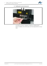
7.2 Adjust the pipette size to the component
Select the largest possible pipette for the component.
ü
If necessary, replace the pipette:
a) Wait for the heating head to cool down.
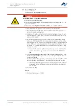
CAUTION
Risk of burning due to heated machine parts and PCB!
All heated machine parts as well as the surrounding housing parts and product sup-
port frame, the circuit board and the components become hot even during warm-up
to the process temperature [Tinit]!
Parts are particularly hot during the soldering process! After the soldering process,
wait until the device and the PCB have cooled down and reached non-hazardous tem-
peratures!
a) Switch to tab [Rework].
b) Click tab [Manual Mode] to view the button row for manual operation.
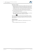
c) Click the “Pipette” pushbutton
9
10
11
12
13
ð
A submenu with further pushbuttons is displayed:
d) Press the pushbutton (10) until the pipette and its holder have moved far
enough downwards.
e) Screw on the pipette and tighten it only slightly
For this purpose, please also read Chapter Spare parts where you can find a list of
available pipettes.
Ersa GmbH
Operating_instructions HR 500 DE 3BA00246-01 | Rev. 1
99 / 124


