5 | Commissioning
Calibrate the pipette distances and the optical axle
Rework
Archive
User administration
Profile management
Administration
Manual Mode
Desoldering
Name
Placement
Profile settings
Search
Heater config
Information
Board
Component
Control sensor
Adaptor (head)
Dip mode
Placement mode
Drop height
TC1
Distance 50 mm
No automation
Placement
Heating head position
Placement
Time
Soldering
Inspection
Soldering
Desoldering
Synchronize
Process automation
Combined
Nozzle
START/REFERENCE
Pickup mode
Component tray
Desoldering
Inspection
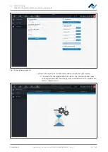
Fig. 9:
Tab [Rework ] in the administrator view. Example picture.
b) If still no suction nozzle is screwed onto the pipette, apply a 5 mm or 10 mm
suction nozzle. For this purpose, please read Chapter Adjust the pipette size to
the component.
Calibration Step 1: Calibrating the pipette distances through function
[Start device setup]
a) In the header, select tab [Administration].
b) In the left menu bar, select menu item [Device options].
Ersa GmbH
Operating_instructions HR 500 DE 3BA00246-01 | Rev. 1
43 / 124


