6 | Function description
Editing the soldering profile in the [Profile management] tab and changing it permanently
6.8.3 The tabulators [Information], [Heating setting] and the arrow key [Image
processing]
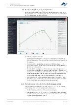
When the [Heater config] tab is called up, the chart (4) with the heating curves is
displayed in the middle of the screen, and below the line with the buttons for the
[Process automation ] (6).
The heating curves in the middle of the screen can be adjusted for the desired sol-
dering process. With regard to this, please read Chapter The chart in the [Rework]
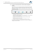
tabulator. You can also change the buttons in the [Process automation] line (6) at
the bottom at any time. With regard to this, please also read Chapter The [Process
Automation] button row [
66]. These buttons enable or disable any process steps.
All the changes performed in the [Rework] tab will be accepted but not saved. If
you switch from the [Rework] tab to another tab, all changes will be lost.
On the bottom right there is the [START/REFERENCE] button, which starts the re-
work process. Make sure you have made all settings correctly before starting the
rework process. How to perform the soldering process is described by way of ex-
ample in the Tutorial – Soldering or unsoldering a component.
The correct soldering profile settings should be specified in the [Profile manage-
ment] tab beforehand. Only possible as “Administrator” user. With regard to this,
please read Chapter The tabulator with the small arrow key (Image processing) un-
der the [Profile management] tabulator.
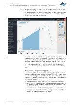
6.8.3.1 The [Information] tabulator under the [User management] tabulator
The heating curves in the middle of the screen can be changed. Also the buttons in
row [Process automation] can always be changed. Use these buttons to enable or
disable process steps.
Rework
Archive
User administration
Profile management
Administration
Manual mode
Soldering
Desoldering
Name
Placement
Profile settings
Search
Heater config
Information
Board
Component
Control sensor
Adaptor (head)
Lens
pipette
Dip mode
Placement mode
Drop height
TC1
Distance 50 mm
L-head
Pipette 1
No automation
Placement
Heating head
Heating head position
Placement
Inspection
Soldering
Inspection
Desoldering
Soldering
Desoldering
Synchronize
Process automation
Combined
Ersa GmbH
Operating_instructions HR 500 DE 3BA00246-01 | Rev. 1
76 / 124


