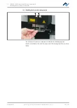
7 | Tutorial – Soldering or unsoldering a component
Task 1 “Alignment”
7.7 Task 1 “Alignment”
The unit will first perform a reference run.
DANGER
Laser beam! Risk of injury due to retinal burns
a) Do not stare into the laser beam!
b) Do not point the laser beam at other people! Reflecting surfaces under the laser
generate reflections!
c) Class 2 laser according to DIN EN 60825-1:2008-5, P < 1 mW, λ = 650 nm
a) Slide both the heating head and the Visionbox in central position.
ü
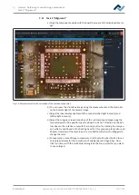
The position laser is switched on. You are asked to set the work position ex-
actly in the middle with the laser.
a) Hold down the button on the front of the bottom heating and move the bot-
tom heating by the side handles, until the laser detects the component to be
soldered in the middle.
b) Set up the temperature sensor. Fit the holder of the temperature sensor in
such a way that the end of the thermocouple can be placed very close to the
component. Shape the end of the thermocouple so that the frontal three milli-
metres of the wire lie in close proximity of the component on the PCB. For ex-
act values, the thermocouple should be in contact with strip conductors, e.g.
circuit path or mass.
ð
You can further connect optional temperature sensors for additional tem-
perature information, e.g. on adjacent components or the PCB bottom
side.
c) If the component is positioned exactly under the laser, follow next work step.
Click button [Next] in the upper window or press the green “Next” button on
the bottom heating.
To interrupt the soldering process, you can always press the red button on the
bottom heating or click the white “X”-marked button in the upper window.
ð
The selected desoldering process starts and the progress can be followed
in the chart. At the end the pipette picks up the desoldered component
from the PCB.
d) Go to the next step.
Also see
2
Ersa GmbH
Operating_instructions HR 500 DE 3BA00246-01 | Rev. 1
105 / 124


