7 | Tutorial – Soldering or unsoldering a component
Position a thermocouple
7.3 Position a thermocouple
3
2
5
6
1
4
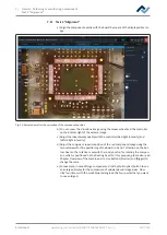
Fig. 21:
Example images: Placing the thermocouple holder (top) and the thermocouple (bottom)
a) Insert the holder (3) into one of the holes (4).
b) Fasten the holder with the lever (6).
c) Insert the plug of the thermocouple (2) the socket [TC1].
d) Slide the thermocouple into the holder (1).
e) Fit the holder (1) in such a way that the end of the thermocouple (7) can be
placed very close to the component.
f) Straighten the end of the thermocouple so that the front 3 millimetres of the
wire lie in close proximity to the component on the PCB.
For exact values, the thermocouple should be in contact with conductive trace
areas, e.g. trace or mass.
Note: The infrared sensor is not suitable for glossy and reflective surfaces.
Ersa GmbH
Operating_instructions HR 500 DE 3BA00246-01 | Rev. 1
100 / 124

