20
EN
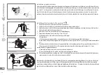
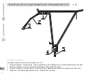
Installation instructions for support wheels – applies to kids bicycles
The rear wheel axle is set and tightened with countering nuts. Installation (removal) of support wheels does not influence its adjustment. In order
to install support wheels, Fig. 73, one has to:
1. Remove nuts (4) from the rear wheel.
2. Remove the mudshield bracket (3) (if present), do not remove adjusting handles (1).
3. Install in the order: wheel arms (2), mudshield support (3).
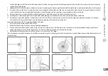
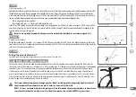
4. Adjust the support wheels so the clearing between the wheels and the ground with a vertically set bicycle was max. 25 mm, Fig. 74. Tighten
nuts (4). Tightening torque – 17 Nm.
5. Caution! Kids bicycle with support wheels may be used in flat terrain, under supervision of adults. Danger in case of a bicycle equipped with
support wheels may also be posed by barriers in the form of poles, narrow gates that the user can catch. Riding with support wheels in uneven
terrain or close to pole-like barriers poses risk of bicycle tipping and as a consequence – injuries resulting from them.
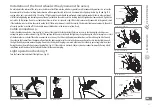
To remove the retaining rings drawing 73 you should:
1. Remove the nuts (4) of the rear wheel axle,
2. Remove the fender supports (3) (if any),
3. Remove the support wheels (2), do not remove the retaining clamps (1)
4. Install the fender supports (3), and then tighten the nut (4) with a torque of 17 Nm.
BASKETS
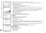
Installation of a basket handle with a latching clip
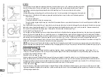
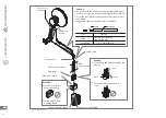
In order to install the basket handle with a latching clip, Fig. 75.:
1. Tighten fixing screws with a 5-8 Nm torque.
2. Set the angle of yoke tilt.
3. Tighten yoke fixing screws with a 5-8 Nm torque.
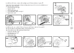
Installation of a basket with a support installed on the front wheel axle
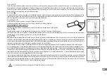
1. Install the basket support onto the front wheel axle (with the profiled arch on the side of the lighting set) in the following order: hook washer,
basket support, nut, Fig. 76.
2. Install the basket on the basket support installed on wheel axle using MS screws, screwing the screws in from the inside of the basket into the
installation metal sheet, installed underneath the basket support, Fig. 77.
3. Place the basket at the desired angle and install from the inside using the set: MS screw, washer and a nut.
FOLDED FRAME
Removal of folded frame lock
In order to remove the folded frame lock:
1. Unblock the lever, Fig. 78.
2. Move the lever, Fig. 79.
3. Fold the frame arm, Fig. 80.
Fig. 77. Basket installation on the support
installation
metal sheet
Fig. 76. Basket support installation (fork hook)
fork hook
Fig. 75. Basket support installation
tighten fixing
screws
tighten yoke fixing
screws
set the yoke
tilt angle
mm
Fig. 74. Minimum clearance of support wheels
from the road
Fig. 73. Installation instruction for support
wheels

