16
EN
Installation of the front wheel with a disc brake
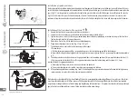
1. Unpack the front wheel, remove the protective caps of axle nuts.
2. Loosen the axle nuts and insert the wheel between the friction linings of brake caliper.
3. Tighten the axle nuts with 25-35 Nm torque, remembering about axial wheel positioning in relation to the legs of the front fork.
Tighten the right and the left nut simultaneously.
4. Rotate the wheel to check if the brake has been adjusted properly.
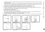
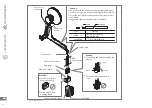
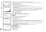
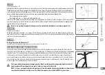
5. Proper brake adjustment, front, wheel, Fig. 53, Fig. 54, Fig. 55.
I. The braking disc does not scratch the friction linings of the caliper.
If friction occurs:
a) Perform adjustment using knob No 1, setting friction surfaces of the caliper lining parallel to the brake disc.
b) Loosen the braking line screwing the brake lever regulator in or screwing screw No 2 out – preserving the condition described in
p. II.
II. The distance between the brake lever and the grip on handlebars in the working position after pressing the brake with force (15-
20 kg) may not be smaller than 10 mm. The suggested distance between the friction lining and the caliper 0.5-1.0 mm.
In order to adjust the appropriate distances:
a) Loosen the line fixing screw, increase tension and screw the line back.
b) Screw in/out the adjustment screw No 2 in order to achieve appropriate distance.
III. After performing adjustment according to p. I and II, the braking distance is preserved and potential friction of braking elements
requires running in in order to have the elements properly adjusted.
Brake levers may be adjusted to the size of hands of the cyclist, ensuring optimum braking efficiency. In most cases, the adjust-
ment is performed using a small Allen screw or a Phillips screw located in the housing of the brake lever. Brake lever motion
range becomes longer with wear of brake lining and lengthening of the brake line – it requires the adjustment to be performed
again. Contact an authorised Kross service station in order to replace worn linings.
Fig. 54. Brake adjustment
adjustment knob
installation screw of
friction linings
adjustment knob #2
caliper installation screws
Fig. 53. Brake adjustment
caliper
adjustment knob #1
friction linings
0,5-1,0mm
0,5-1,0mm
Fig. 55. Brake adjustment
caliper
0,5-1,0 mm
0,5-1,0 mm
disc
friction linings
»
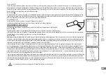
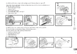
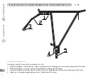
Fig. 52.2
Installation of spoke protectors
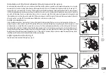
In order to prevent wheel rotation interruption or stopping in case of improper switch adjustment or switch damage (in case of bicycles with the rear
switch), the bicycle should be equipped with a spoke protector. In case of bicycles with slow gear, its installation is performed by unscrewing the slow
gear 3, Fig. 52.1, next the protector in installed on the axle and the slow gear is installed with a 40-50 Nm torque. In case of bicycles with a cassette,
Fig. 52.2, the last ratchet of the cassette 4 must be removed, all ratchets 3 must be removed, place protector 2 on axle barrel 1 in such a way that
protrusions in the protector and on the axle match each other, then install all ratchets and tighten the last one with torque engraved in the element.

