background image

27

EN

NOTES

Summary of Contents for Le Grand Annie

Page 1: ...INSTRUCTION MANUAL ...

Page 2: ...g pre sales actions 01 Bicycle unpacking 02 Installing pedals and their thorough tightening 03 Adjusting and tightening handlebars in position ready for riding 04 Tightening all screws 05 Checking lightning and tyre positioning 06 Brake and switch adjustment 07 Pulling spokes up and centering wheels if necessary 08 Filling air in tyres to the desired pressure 09 Removing traces of contamination an...

Page 3: ...ake disc brake Braking disc Spoke Crank Crank mechanism with chained wheels Chain disc Seat Seat support Seat support lock quick clipper Underseat pipe Rear wheel shock absorber Joint Rear triangle upper pipe Rocker Shifter Cassette low gear Shifter line Shifter mechanism Rear triangle lower pipe Shifter mechanism rollers Rear wheel Chain Front wheel ...

Page 4: ...2 EN ...

Page 5: ... designed for save travels down the streets in the cities They combine comfort and functionality This type of bicycles and in particular their brakes have been designed for a maximum load not exceeding 125 kg cyclist bicycle luggage where the weight of the cyclist and the luggage together cannot exceed 105 kg CROSS AND COMFORT universal and multifunctional Designed for riding on gravel and asphalt...

Page 6: ...rims with andwithout the groove i CLASSIC Madison Madison bike inspired by the classic models from the 50 s is a unique combination of style and ergonomy Now you can feel the joy of bike ride and admiration of amazed passerby COMFORT Pave Pave bike was designed epecially for recreational use Its construction guarantees comfort of ride in concrete jungles on the parc paths and forest trails CRUISER...

Page 7: ... mainly to the frame the front fork the seat support brakes levers clips discs linings cables chain pedals cranks axle of the crank mechanism and the rim thus it is suggested to check these elements periodically 14 Children below 12 years of age should ride a bicycle only accompanied by an adult parent or carer 15 Riding a bicycle after alcohol consumption and under influence of drugs is dangerous...

Page 8: ...ts attached to it from the box seat basket pedals handlebars wheels and mudshields Detach the handlebars from the frame by removing the securing clipping bands 2 Remove the lower part of the handlebars support in the stem of the fork so the line limiting maximum protrusion is not visible Tighten the support with a dynamometric key using moments listed in this manual setting the handlebars perpendi...

Page 9: ...rs attached they must be installed at the ends of the handlebars parallel to each other Suggested inclination of the horns is ca 45 degrees After adjustment the horns of the handlebars must be tightened using moments defined in this instruction Fig 7 In case of a bicycle with TDS type handlebars Ahead 1 Take the bicycle and attached elements out of the box 2 Unclip the handlebars from the frame by...

Page 10: ...Tighten yoke screws with the moment engraved in the component then according to moments listed in this manual In case of bicycles with full shock absorption one has to pay attention to the minimum seat height The bracket set in too deep may hit the elements of the back rocker arm during operation NOTE In case of bicycles with frame made of carbon carbon fibre the seat support must be seated in the...

Page 11: ...he ride comfort In shock absorbing forks depending on the model one can perform just a few adjustments of the initial tension defining hardness of the fork pressure damping defining how quickly does the fork deflect decompression damping defining how quickly the forkreturns to the initial position These adjustments are made using easily available knobs installed at the top of the legs of the fork ...

Page 12: ...e tyre after complete compression of the fork 4 Pump the fork again Remember than using the mudshield limits access Repeat the tyre accessibility test to check if the distance is appropriate After each tyre change this test should be repeated In case of shock absorbers in which the spring is the working element contact an authorised service station in order to perform the tyre distance test Fork m...

Page 13: ...nd range regulation tightening top lids of the air valve by greasing inspection for air leaks torque tightening control adjusting topersonal preferences of the cyclist Information about the locations where 1st and 2nd services are performed can be obtained in an authorised service station Shock absorber adjustment BLOCKING SYSTEMS The function of blocking forks is designed for minimising bicycle w...

Page 14: ...e rim however in such a way that the back of the pad was ca 2 mm further away from the rim than the front of the pad Fig 25 Please pay attention that the pad does not touch the tyre during braking and was pressed to the rim along its entire surface If the brake arms do not return on their own clean and grease fixing points to the fork or to the frame or replace lines or shields The brake handle sh...

Page 15: ...list may fall off the bicycle In order to avoid this slow down earlier and use the brake delicately Before starting the ride always make sure that front and rear brakes are operational Prevent penetration of oil or grease into the disc or brake clutches otherwise the brakes may not operate correctly If any grease or oil makes contact with the pads the pads must be replaced If any grease or oil mak...

Page 16: ...t Depending on the conditions and rides frequency the chain is wearing out and increases its length at the same time damaging the ratchets In order to check the proper tensionofthechain setthegearsinsuchawaythatthechainislocatedonthebiggestrearratchetandonthebiggestdiscinthefront Next trypullingthechainawayfrom the disc If the chain reaches a distance of more than 3 mm it must be replaced Turn to ...

Page 17: ...he desired air pressure If the air chamber valve cartridge needs to be replaced then in the case of AV type valves a special spanner is required Fig 51 Other valves are replaced by unscrewing the nut replacing the cartridge and screwing the nut back on A securing nut is also necessary lack of which may result in air losses Some wheels are constructed on the so called wide axle Removing them from a...

Page 18: ...the braking distance is preserved and potential friction of brakingelements requires running in in order to have the elements properly adjusted Brake levers may be adjusted to the size of hands of the cyclist ensuring optimum braking efficiency In most cases the adjust ment is performed using a small Allen screw or a Phillips screw located in the housing of the brake lever Brake lever motion range...

Page 19: ...cratched off It is advised to connect both cables so the current may flow freely Cable connection Cables should be connected as shown on Fig 63 Connect the cable to the fork or basket fixture in such a way that during the ride it does not entangle in spokes or other elements Fig 60 If the position of the axle in relation to the light may change during the ride for example as a result of shock abso...

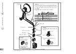
Page 20: ...iented Move 16 mm closer Lamp cable Caution Do not reverse the frame cable and the light cable If the cables are connected incorrectly the light will not turn on Cross the cables before connection so they create a cohe sive whole Suggested cable specification cable insulation Cable Insulation Type Cable Insulation groove insert Caution Cross cables and lead them along the grooves cross The cables ...

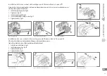
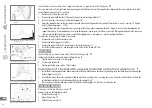
Page 21: ...hange system Fig 67 5 Tighten the brake Fig 68 After wheel installation removal problems with proper switch operation may occur Contact the authorised service station in order to perform adjustment 1 Latch the line in the handle Fig 69 2 Install adjusting washers Fig 70 3 Tighten the nuts Fig 71 4 Tighten the brake Fig 72 Installation of a rear wheel with a multi gear axle Shimano Nexus 7 8 speed ...

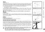
Page 22: ... Install the fender supports 3 and then tighten the nut 4 with a torque of 17 Nm BASKETS Installation of a basket handle with a latching clip In order to install the basket handle with a latching clip Fig 75 1 Tighten fixing screws with a 5 8 Nm torque 2 Set the angle of yoke tilt 3 Tighten yoke fixing screws with a 5 8 Nm torque Installation of a basket with a support installed on the front wheel...

Page 23: ...rn the pedal counterclockwise PEDALS Setting the adjustable stand Stretch the stand at the appropriate length so the bicycle stands on its own Fig 80 and Fig 81 STAND Fig 80 Stretching the support out Fig 81 Stand adjustment 8 0 0 CLEANING AND MAINTENANCE The bicycle must be maintained in good technical condition and the user must remember about regular cleaning The bicycle must be cleaned after e...

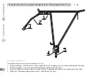
Page 24: ...er installation tightening with 6 8 Nm torque 2 Metal pad connecting pos 3 or bars pos 2 connect with the bicycle frame tightening with 6 8 Nm torque 3 Screw carrier supports to the lower part of the frame using M5 or M6 screws depending on the holes in the frame tightening with 6 8 Nm torque 4 Fixing bar pos 2 with appropriate opening of connector pos 1 tightening with 6 8 Nm torque Fig 78 Instal...

Page 25: ... Joint elements should be correctly tightened and often checked The carrier is not adjusted for pulling a trailer The reflexive light or the light may not be covered by the luggage All mobile parts of the luggage should be secured against entangling in the wheel The luggage should be uniformly placed on both sides of the carrier Caution Check if geometric data and durability of the bicycle on whic...

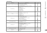
Page 26: ...ngs and increases fluidity of shock absorber operation For external working surfaces upper legs in front shock ab sorbing forks a small amount of lubricant for shock absor bers not containing lithium can be applied Underseat pipe After each taking out Bearings lubricant or thick chain lubricant Apply a small amount of lubri cant on the surface entering the frame Pedals Once a year Bearings lubrica...

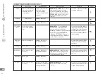
Page 27: ...axis Loose or bent support Bent crank Loose pedal bearings Squeaking noises Not oiled axle bearings or support The seat makes squeaking noises Not oiled rotation axes in rear wheel suspension Rusty or not oiled chain Not oiled shock absorbing fork Not oiled shock absorbing support The switch hits the spokes Incorrectly adjusted rear switch Bent rear switch Screeching noises Not oiled handlebars br...

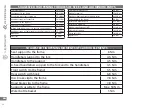
Page 28: ...pport 15 20 Nm Front and rear wheels nuts 25 35 Nm A head handlebars support to the fork and handlebars 8 12 Nm Handlebars support adjustable at the adjustment location 15 20 Nm Brake pads 6 9 Nm Line clips 5 8 Nm SUGGESTED TIGHTENING TORQUES OF STEEL AND ALUMINIUM PARTS SUGGESTED TIGHTENING MOMENTS OF CARBON ELEMENTS Seat support to the frame 6 Nm Handlebars support to the fork 4 6 Nm Handlebars ...

Page 29: ...27 EN NOTES ...

Page 30: ...ll its elements are protected by Polish and international law in particular in currently effective Act on copyright law and similar laws Printing and copying using printing or digital techniques modification and distribution of materials contained in thisWarranty card User manual in part or in entirety for purposes other than non commercial ones is possible only after obtaining approval of KROSS S...

Page 31: ...RAM COM KROSSBIKES YOUTUBE COM KROSSBIKESTV FACEBOOK COM LEGRANDBIKES INSTAGRAM COM LEGRANDBIKES WWW KROSS EU WWW LEGRANDBIKES COM CONTACT IN YOUR COUNTRY WWW KROSS PL EN DYSTRYBUTORZY KROSS S A UL LESZNO 46 06 300 PRZASNYSZ TEL FAX 48 29 752 44 45 ...

Page 32: ...Y E A RS WA R RA N T Y Y E A R S W A R R A N T Y 5 5 YEARS WARRANTY ON ELIGIBLE KROSS BICYCLES 5 YEARS WARRANTY ON ELIGIBLE LE GRAND BICYCLES ...

Reviews: