9
EN
Transport
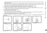
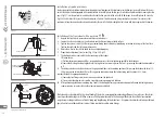
In order to set the handlebars and the wheel in the axis of symmetry of the bicycle (or to prepare one of these elements for transport – twist in relation to the axis
of symmetry) in a system with a wedge one has to loosen the fixing screw at the top of the bracket, and in the a-head system – tightening screws at the side of the
bracket. These screws must be tightened according to moments listed in this manual. In the a-head system, do not unscrew the screw located at the top of the bracket,
which is used for controls regulation, namely, handlebars bearings.
Controls
During bicycle use, loose motions may appear in the handlebars bearings. In order to recognize such occurrence, one must press the front brake and put fingers of the
other hand to the controls and move the bicycle back and forth. If motion between bearings and handlebars bracket or the head of the frame is palpable, the bicycle
must be transported to an authorised service station in order to perform adjustments.
Switch levers
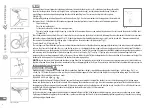
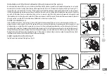
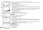
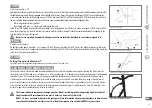
Set the switch lever/brake assembly at an angle of 45 degrees to the ground.
Switch levers (rotating) should be set in such a way that gear numbers are visible in all positions.
SHOCK ABSORPTION
The shock absorption function is provided by many elements. In most cases their operation may be regulated.
Tyres
Depending on the amount of air pumped into the air chambers or tyres (in chamber-free systems), the bicycle may
cover irregular terrain more or less smoothly. The minimum and maximum pressure value is given on the side of the tyre. One has to remember that too low pressure,
although it improves ride comfort, may quickly cause a tyre or air chamber puncture.
Forks
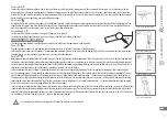
Both rigid and shock-absorbing forks are installed in bicycles. The first type provide shock absorption in a rather limited degree. The latter have been devised in particu-
lar to increase the ride comfort. In shock-absorbing forks, depending on the model, one can perform just a few adjustments of the initial tension (defining hardness of
the fork), pressure damping (defining how quickly does the fork deflect), decompression damping (defining how quickly the fork returns to the initial position). These
adjustments are made using easily available knobs, installed at the top of the legs of the fork.
In shock absorbers, which have springs as operating elements, the suspension is regulated by tightening (harder suspension) or loosening (softer suspension) the
nut. The operating parts of the legs should be cleaned and preserved using aerosol Teflon grease. The shock absorbers (the front fork and shock absorption of the rear
wheel) should be adjusted and preserved according to the user manual. Regulation of fork shock absorption – the adjustment is performed using a knob located in
the top part of the legs of the fork, turning the knob clockwise increases hardness of the shock absorber (ride on even terrain – hardened paths and asphalt), turning
counterclockwise, we cause the opposite effect (for ride in an uneven terrain). Adjustment of rear wheel shock absorbers – for spring shock absorbers, tightening the
nut results in results in an increased spring stiffness (for rides on even roads).
In case of hydraulic shock absorbers, adjustment is performed using an adjustment knob, tightening results in increased stiffness, loosening – decreased stiffness of the
shock absorber. In case of shock absorbing brackets, the adjustment must be made using a 5 or 6 mm Allen key, turning the screw located at the bottom of the shock
absorber (after taking the pipe out of the underseat frame). Making a clockwise turn shall increase bracket hardness. Do not loose the screw so at least 2-3 thread lines
are invisible on the internal side of the bracket – this may lead to bracket damage.
Use a protective mask when spraying grease. Perform these works in a ventilated area.
!
45
0
Fig. 12. Seat position adjustment
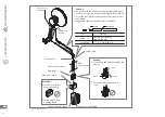
Fig. 13. Support with a wedge
Fig. 14. A-head type support
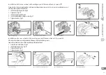
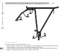
Fig. 15. Shock absorbing fork


