3.3.3 Frequency (pulse) output F
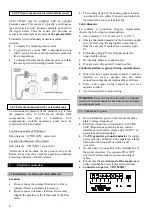
The frequency output is galvanically isolated
from all input and output circuits but
not
from current output I.
Therefore only one grounded receiver instrument may be connected to either frequency output F or current output
I.
·
·
·
·
·
·
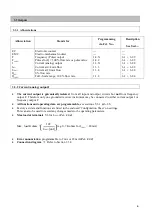
All functions and operating data are programmable,
see Section 5, 6.1 & 6.2.9.
Factory - set data and functions
are listed in the enclosed report on settings. This can also be used to record any
changes made to the operating parameters.
Active frequency output
for electromechanical totalizers
EMC
(terminals 4.1/4.2) or for electronic totalizers
EC
(terminals 4.1/4.2 or 4/4.1/4.2), 10 to 36000000 pulses/hr (0.0028 to 10000 Hz), amplitude max. 30 V, selectable
pulse widths and load rating see below.
Passive frequency output,
open collector for connection of active electronic counters EC or switchgear, input
voltage 5 to 30V, load current max. 100 mA, R
i
= 100 ohms, selectable pulse widths see below.
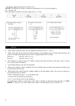
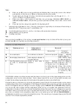
Pulse width (
Fct. 1.4.3
)
as a factor of frequency f (pulse rate) and
maximum permissible load for active output
(term. 4.1/4.2 or 4/4.1/4.2), see also Sect. 6.2.9.
Pulse width
Frequency f = F
100%
Load rating of active output
Load current
Load
500 ms
0.0028 Hz
< f
£
1 Hz
< 150 mA
³
160 Ohm
200 ms
0.0028 Hz
< f
£
2 Hz
< 150 mA
³
160 Ohm
100 ms
0.0028 Hz
< f
£
3 Hz
< 150 mA
³
160 Ohm
100 ms
3 Hz
< f
£
5 Hz
< 60 mA
³
400 Ohm
50 ms
0.0028 Hz
< f
£
5 Hz
< 150 mA
³
160 Ohm
50 ms
5 Hz
< f
£
10 Hz
< 60 mA
³
400 Ohm
30 ms
0.0028 Hz
< f
£
6 Hz
< 150 mA
³
160 Ohm
30 ms
6 Hz
< f
£
10 Hz
< 80 mA
³
300 Ohm
Pulse duty cycle 1:1*
10 Hz
< f
£
1000 Hz
< 25 mA
³
1000 Ohm
160 µs*
1000 Hz
< f
£
2547 Hz
< 25 mA
³
1000 Ohm
50 µs*
2547 Hz
< f
£
10000 Hz
< 25 mA
³
1000 Ohm
* fixed pulse width, independent of programming in
Fct. 1.4.3
Refer connection diagrams
k
,
l
and
m
. Refer to Section 3.3.4
·
·
Output characteristics
3.3.4 Connection diagram for outputs
j
to
m
Current output I: Diagrams I1 in Section 6.2.8
7


