8
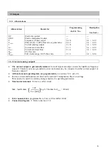
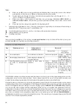
3. Frequency output F: Diagram F1 in Section 6.2.9
R1 & R2
when electronic counter is connected to terminals 4/4.1/4.2 connection diagram
l
R1 = 1 Kohm , 1W
R2 needed only for totalizer with input voltage Umax < 30 Volts.
Umax
24 V
12 V
5 V
R2
3.9 Kohm
680 ohm
180 ohm
4. Start-up
Check that the system has been correctly installed as described in Sect. 1, 2 and 3.
·
·
·
·
·
·
Before initial start-up check that the following details on the nameplate agree with the data specified in the
report of settings for the signal converter. If not, reprogramming will be necessary.
Meter size
Fct. 3.1.1
Sect. 6.1, 6.2.5.
K-Factor
Fct. 3.1.2
Sect. 6.1, 6.2.5.
The flowmeter is ready for service 15 minutes (waiting time) after switching on the power source. Increase
flow velocity slowly and steadily.
Avoid abrupt changes in pressure in the pipeline.
If the process product is steam, condensate may form initially and cause faulty measurements when the system
is started up for the first time.
When powered, the signal converter normally operates in the measurement mode. The power-on sequence to
measurement mode is as follows :
‘TEST
’ is displayed for approx. 3 seconds followed by
‘
VFM 5090
’ the instrument type followed by
‘
Ver x.xx
’ the software version of the instrument.
Then instrument operates in measurement mode where it displays the parameter being measured or ‘
FATAL
ERROR
’ if there are one or more critical errors detected (For description on errors refer Sect 5.5)


