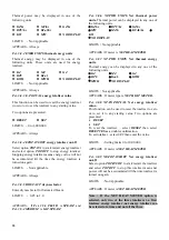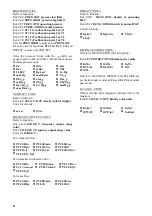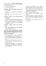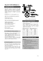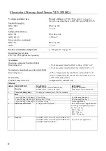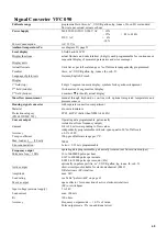
Display functionality can be checked by the use of
Fct. 2.1 TEST DISP.
This function tests all the segments of the display in
the following order. Alphanumeric field, numeric
field, arrow and key markers. For details refer Sect
5.4 + 6.1.
Fct. 2.2 TEST I
can be used to test current output
function of VFC 090. With this function it is possible
to generate following test values
0/2/4/10/20/22 mA
Current output electronics is factory calibrated and
should be /- 0.02mA. Otherwise re-
calibration of current output is necessary by
KHRONE MARSHALL service person.
Fct. 2.3 TEST F
is meant for checking frequency
output function. The following test frequencies may
be generated
1/10/100/1000/10000 Hz.
Frequency
output signal can be checked on an oscilloscope or a
frequency meter between term 4/4.1 and term 4.1/4.2
with a load resistance of 1k to 2k ohms.
It is assumed in this section that the flowmeter has
already been installed. (for installation details refer
Sect. 2+3)
Following are some trouble shooting hints.
SYMPTOM :
Display is blank.
·
·
Supply voltage (between term 11/12) is not
available.
Mains fuse within the instrument has blown out.
Fuse is accessible only after removal of
electronics from the converter housing. To
remove electronics follow the steps given below :
Always switch-OFF power source before
commencing work!
1.
Use the special wrench to remove the cover
from the terminal box.
2.
Disconnect all the cables from the terminals :
term 5/6/4/4.1/4.2/11/12
3.
Use the special wrench to remove the cover
from the electronics compartment.
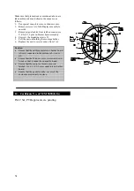
(Refer Fig. on page 43)
4. Remove
screws
A
and fold display board to
side.
5. Remove
plugs
X, Y, Z
to remove wires from
d
pressure sensor, temperature sensor and vortex
sensor respectively.
6. Remove
screws
D
using a screwdriver for
Philips- head screws [size 2, blade length 200
mm (8”) ] and carefully remove the complete
electronics.
7.
Remove the fuse from its black plastic housing
located on
power supply board
for checking.
Replace the fuse if necessary. Rating of fuse is
dependent on line voltage.
7.2.2 Display check
7.2.3 Current output check
Voltage Fuse
Value
Order
No.
220 / 200 / 240 VAC 125 mA
K2023937
120 VAC
200 mA
K2023938
100 / 110 VAC
250 mA
K2023939
8.
Reassemble in reverse order
Important : Ensure that the screw thread of the
covers on the electronic and connection
compartments is well greased at all times.
7.2.4 Frequency output check
Electronics faulty
·
·
·
·
·
·
·
·
·
SYMPTOM :
Current output is not proper.
Check current output electronics (refer
Sect.7.2.3)
Check current output electronics programming of
current output functions
Fct. 1.3.x.
8. Trouble
shooting
hints
Check that current output loop is not overloaded
[700 ohm max.]
SYMPTOM :
Freqency output is incorrect
Check the frequency output electronics (refer
Sect. 7.2.4)
Check programming of frequency output
(Functions
Fct. 1.4.x.
)
Check that frequency output is not overloaded.
For load ratings of frequency output refer Sect.
3.3.3.
SYMPTOM :
Non zero flow indicated when no
actual flow in the pipe.
Mains interference due to improper earthing.
The protective earth PE terminal should be
properly grounded.
Excessive mechanical vibration in the pipe.
If so, support the pipeline near the flowmeter
perpendicular to both the axis of the pipe and the
axis of the bluff body.
SYMPTOM : ‘
CHECK INST.’ error is displayed
when no flow in the pipe
Display should normally indicate 0.0 flow rate,
LOW
FLOW
and
LOW SIGNAL
errors when there is no
48


